| Monthly Tech-Tip | No tracking! No ads! |
0.8mm thickness
This is an ideal wall thickness to print on consumer 3D printer since to normally creates sufficient strength and prints in one two passes
Key phrases linking here: 0.8mm thickness, 0.4mm, 0.8mm - Learn more
Details
It is common for people to leave their 3D printer unattended printing for days (against manufacturer warnings). This is not only wasteful because so much filament is used (and thrown away after use) but also because most prints are not final versions, changes are made and reprints are done multiple times until it is right. In addition, failed prints are common for a host of reasons, this is especially costly in PLA use if it happens after 20 hours.
We place a high emphases on light-weight molds that print quickly. It is almost always possible to design so that walls of 0.8 mm thickness are possible. Larger forms can be done in multiple pieces to this same end. Why 0.8mm? Because most printers have nozzles 0.4mm wide, thus two passes of the print head produce the wall. In many situations the slicer software is smart enough to optimize print head movement to really take advantage of this, thus minimizing the amount of time for each layer.
0.8mm wall thickness has another advantage. It is common to 3D print PLA case molds, into which plaster is directly poured, to make working molds. The thinner the PLA plastic layer is easier it is to remove from freshly set plaster, using a heat gun. It is also safer to remove, there is less likelihood of damage to any delicate plaster edges.
Sometimes we print at 1.2mm where extra strength is needed. Slicers are usually smart enough to do this in three passes. However, for 1.6mm many would zigzag to fill between the outer lines, drastically increasing print time and printer wear and tear.
Related Information
Nursery Plant Pot drawing

This picture has its own page with more detail, click here to see it.
I made the bottom and top radiuses and the height parametric. I made the diameter of the pouring ring = top diameter of the pot + 2 mm. The walls are 2mm thick because my 3D printer prints 0.4mm wide (that means two passes for each layer).
Video: Create a cookie cutter/stamper in 3D software, print it and use it

This picture has its own page with more detail, click here to see it.
This cookie cutter can both cut and stamp the piece (notice the 3D render in the centre, the logo is 2mm lower than the cutter around the outside). We make them by rolling a slab to 3.2mm (1/8in) thick, applying stretch wrap over it and then pressing the cutter/stamper into it (using a wood block). Then just peel away the plastic and the outer waste clay and a perfect crest is left. This method enables using clay of almost any stiffness. We find that softer clay works best, just peel it up from the board, apply slip to the back, position it on the side of the leather hard ware and press it down (from the centre outwards). On the lower right is a crested mug that has just been glazed. Upper right is a crest that has been glazed and fired. About the cookie cutter: We create them with 0.8mm wall thickness (twice the width of the 0.4mm extruder on the 3D printer). We export the vector image (made in Illustrator) into Fusion 360 and then add elements to stabilize and hold the profile in place. This cutter is 8mm tall, and the stamp lines are 5mm tall. The crest is 52mm (2 in) wide. This whole process may sound a little intimidating to you - but we are working on a step-by-step video.
Bone China Anti-Warp Setter test molds

This picture has its own page with more detail, click here to see it.
Straight-sided thin walled slip cast porcelain pieces are very prone to warping. To assure the rim fires perfectly round a fool-proof solution is to fire them upside down on a refractory setter having a ridge that matches the inside diameter of the fired rim (upper right).
On the left you are looking at four objects for 3D printing, each has 0.8mm thick walls (my printer extrudes 0.4mm wide). The bottom shows the inner cup itself visible through the partially transparent outer shell mold. I fill the cup with plaster, extract it, polish and soap the plaster surface and stick it upside down to a smooth surface (using a sticky ball clay slurry). Then I stick the outer 3D printed shell down around the cup form and pour in plaster to make a working mold. Sure enough, thin walled cups cast in that mold all warp when fired to vitrification. By averaging the inside minimum and maximum rim diameters I get the measurement needed to create the setter press mold top left (of course I must factor in the total shrinkage of the refractory L4482B). By pouring plaster into that I get press molds for making the setters.
My Initial CAD Drawing of the Mug
This enabled printing a mock-up

This picture has its own page with more detail, click here to see it.
To make this I offset the profile sketch by 0.88 mm outward, this enables printing a thin shell of the shape. The total shrinkage from forming to the final firing product will be about 10%, thus the 0.88 will shrink down to 0.8 mm, that is exactly double the 0.4mm width of my printhead. I rotated the .88 mm profile to create this shell. In the slicer, I shrunk each of the models by 10% to emulate clay shrinkage.
CAD steps for a 3DP block mold to make a rubber case mold

This picture has its own page with more detail, click here to see it.
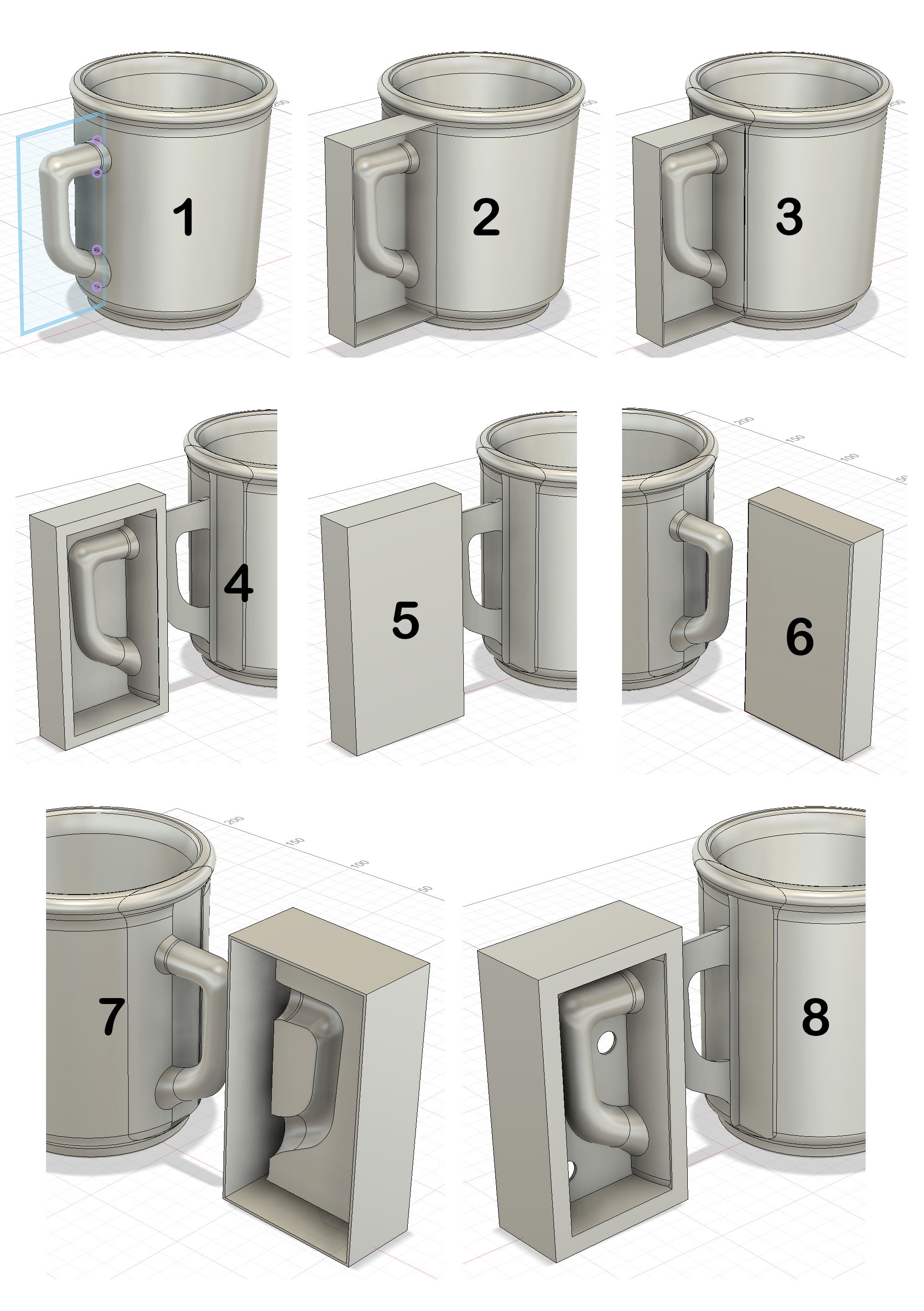
The objective was to make a rubber master case mold for the production of working plaster molds. 3DP is a great solution. This drawing was done in Fusion 360.
1: A make a sketch of a box, around the handle, on the XY plane. Offset that outward by 1.2mm (my printer prints 0.4mm wide, three passes give good strength).
2: Extrude to create box 1: The base backward by 1mm and the sides forward by 20mm.
3: Use five sides of the box as cutting planes to slice it out of the mug.
At this point I could print this in PLA filament, pour plaster into and then use a hair drier to peel it off. But let’s make rubber molds instead.
4: Move the box-with-handle away from the mug. Pull the four sides out by 5mm to thicken them.
5 & 6: Create box 2 around the outside of it, as a new body, 1.2mm wider and taller, 1mm more frontward and 1mm less backward.
7: Use box 1 as a cutter to remove material from box 2 and then pull the outer 1.2mm sides 5mm backward.
8: Shell out the back side to 1.2 wall thickness and make two 9.4mm holes (to accommodate natch clips).
To make side 2 mirror-image a new body using the front or back as the reflexion plane. The back side is then filled with PMC-746 rubber to make the block mold. Plaster is poured into that to make each working mold.
Flanges enable an all-in-one 3D printed block mold for slip casting

This picture has its own page with more detail, click here to see it.
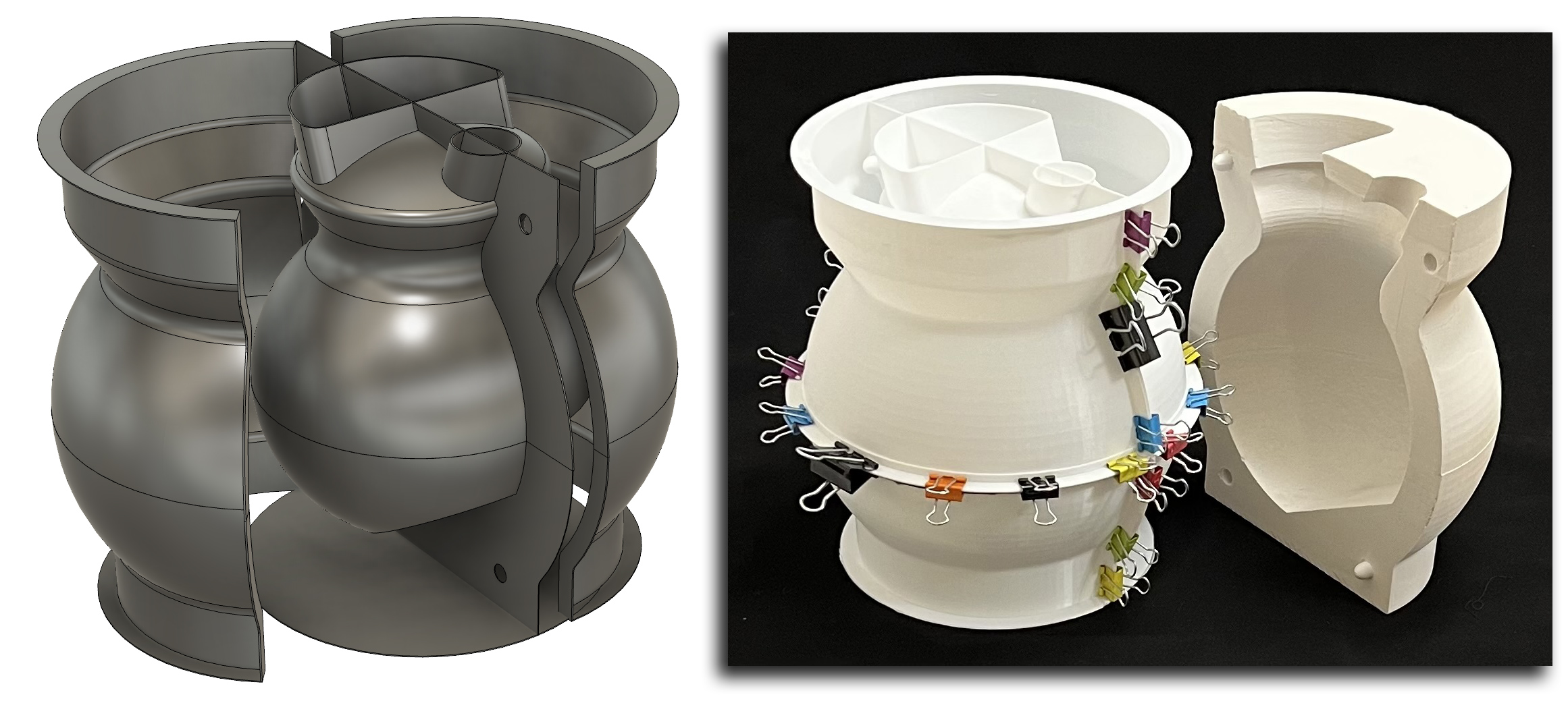
The center piece of this 3D printed assembly defines the outside shape of the ceramic vessel (plus two spares at the top). This entire assembly is an all-in-one case mold for a two-piece plaster working mold. This was printed as six light-weight units on standard Prusa MK3 and MK4 printers, walls are 0.8mm thickness. The upper and lower inside model halves were glued together (with the aid of an inside hoop to line them up). Outer flanges were glued on to enable clamping the outer shell vertically and horizontally.
The membranes defining mold mating points are printed onto the inside model, they extend out far enough to clamp between the flanges of the outer shell sections (suspending the model in the center). The membranes have holes to enable inserting natch-pairs. The thin base is glued on to hold the lower outer shells in place (in flexes enough to enable extracting the plaster form without mold breakage). The whole assembly is held together by clamps so it can be used multiple times.
Inbound Photo Links
 3D printed three-piece jigger case mold complete |
Links
| Glossary |
Infill and Support
Infill and support are structural elements that 3D slicer software uses (e.g. to fill the interior of solid parts or support contours over empty space) |
| By Tony Hansen Follow me on        |  |
Got a Question?
Buy me a coffee and we can talk

https://digitalfire.com, All Rights Reserved
Privacy Policy
