Mold Shell Flange
Learning to create flanges in CAD design enables a new kind of DIY mold-making for ceramics: 3D-printed lightweight reusable molds that clamp together.
Key phrases linking here: mold shell flange, flanges - Learn more
Details
Many issues must be dealt with when using consumer 3D printers for mold-making in ceramics. One of these relates to size: Molds that could otherwise be printed as one large piece have to be done in multiple pieces because the printer is not big enough. The second issue is print times: A print failure on a large piece that might take a day or more to print is obviously as disaster. But what if that mold could be just a thin shell instead of a thick and bulky monstrosity? Designing in flanges so that pieces can be clamped together is the answer. Printer filament and print times are so greatly reduced using this method that you will never go back! A further benefit is that printed shells can be reused.
Related Information
Creating a flange on a 3D printed two-half shell mold

This picture has its own page with more detail, click here to see it.
Upper left: If this mold is too big for a 3D printer or needs to be reusable then it must be printed in two halves (with flanges for clamping). Here is how to create the vertical flanges on the ends.
The secret is revolving twice, once with the wall and flange and a second time using a cut operation with only the flange.
Top right: The sketch is visible and includes both the 0.8mm wide mold wall (and top flange) and the vertical 5mm wide vertical flange.
Bottom left: Both flange and wall are being rotated as a new body 180 degrees (-180 for the back half).
Bottom right: The flange itself is being revolved with partial extent type, and from two sides, using the cut operation and from -179.3 to 0.7 degrees. How did I know these numbers? Experimentation. The Fusion 360 Inspect menu has a measure tool. I kept trying different numbers until I got a flange about 1.2mm wide.
This method could also be used for three or more pieces. Also for one piece that can be opened enough on one side to release (using an initial 359.5 degrees and that a second cut to leave the two flanges).
v1.0 3D-printed flanged rail to cast working plaster jigger molds
This picture has its own page with more detail, click here to see it.
The multi-use grey outer rail on the left was printed in two parts and glued together at the shoulder (to avoid the printing of support). The wall thickness is 1.6mm, actually too thick for fast printing. For v2.0 we went to 1.2mm and printed it upside down, in one piece, on a flange (this generated support but new printers to that so well that the step disconnects well and is not rough). The vertical split enables opening the shell a little after the plaster has set, quickly releasing it. The center model, of the inside contour of the mug, is integrated into a two-step base, it was made by casting the plaster inside another two-piece 3D-printed form. After removing that using a heat gun, I smoothed the plaster surface using a metal rib and trimming tool and then soaped it to ready for a pour. The mold shell is held securely in place by stretching a wide rubber band around the first step and clamping the shell into place around it. The assembly is then ready to be filled with plaster to make a jigger mold. Doing this on a turntable is also a good idea - it enables rotating it while filling and agitating after full to dislodge any air bubbles.
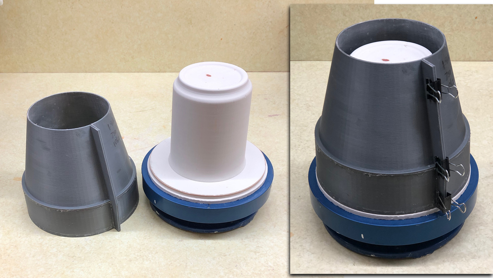
v2.0 3D-printed flanged rail to cast working plaster jigger molds
Available on the Downloads page

This picture has its own page with more detail, click here to see it.
This enables casting a plaster mold that drops down in our aluminum jigger wheel cuphead. The critical measurement is the 73mm radius of the step where the mold sits inside the cuphead (this must be adjusted to your cuphead). To use, turn this upside down and center it over a plaster or 3D printed form of the inside shape of the vessel. The outfacing flanges enable this shell to open enough to release from the jigger mold being cast. Using paper clamps it is held together, and held down to, a clamping baseplate (having 86.2mm radius, it is a separate drawing). To assure that the mold seats well into the cuphead and rotates true, adjust the inner radius of the spacer ring and print it.
Flanges enable an all-in-one 3D printed block mold for slip casting
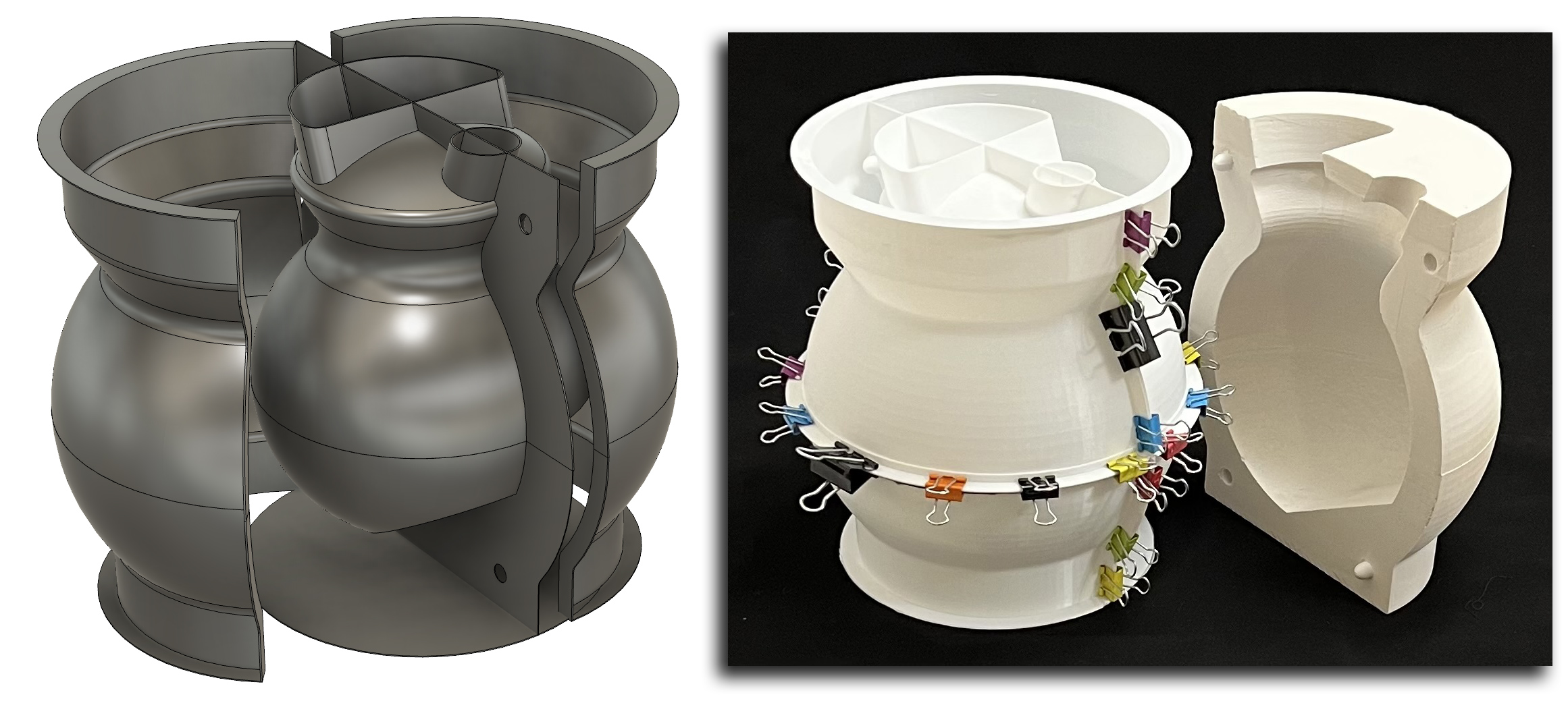
This picture has its own page with more detail, click here to see it.
The center piece of this 3D printed assembly defines the outside shape of the ceramic vessel (plus two spares at the top). This entire assembly is an all-in-one case mold for a two-piece plaster working mold. This was printed as six light-weight units on standard Prusa MK3 and MK4 printers, walls are 0.8mm thickness. The upper and lower inside model halves were glued together (with the aid of an inside hoop to line them up). Outer flanges were glued on to enable clamping the outer shell vertically and horizontally.
The membranes defining mold mating points are printed onto the inside model, they extend out far enough to clamp between the flanges of the outer shell sections (suspending the model in the center). The membranes have holes to enable inserting natch-pairs. The thin base is glued on to hold the lower outer shells in place (in flexes enough to enable extracting the plaster form without mold breakage). The whole assembly is held together by clamps so it can be used multiple times.
Belt and suspenders baseplate for 3D printed molds
Available on the Downloads page

This picture has its own page with more detail, click here to see it.
This solves several problems with hobby casting of plaster in 3D-printed shell molds: Plaster leakage, mold reuse and ease of assembly and disassembly. This assembly is the bottom half of a 3D printed 0.8mm wall thickness PLA mold having flanges for clamping. Plaster exerts a lot of pressure, especially in deep molds, even super gluing a disk onto a bottom flange can fail and result in a plaster spill. This is a "belt and suspenders" solution. This disk is thick and strong and paper clamps hold it onto a flange on the sidewall of the mold pieces. These recesses enable placing it flat onto a level table.
Side Rails For v1 Working Mug Mold

This picture has its own page with more detail, click here to see it.
In this approach to making a prototype mold I have poured plaster into a 3D printed block mold (and done minimal surface treatment to smoothen it). This produced the plaster case case mold shown here. These side rails were made specifically to fit it. For rigidity I printed their wall thickness at 1.2mm. The flange at the bottom fits under the mold and helps assure that no plaster will leak under and displace it upward (provided, of course, that the plaster form is held tightly in place within the rails).
Links
| Glossary |
Infill and Support
Infill and support are structural elements that 3D slicer software uses (e.g. to fill the interior of solid parts or support contours over empty space) |
 PayPal | No tracking, No ads, No paywall, No transient content! Just organized, concise information constantly updated and improved. Was this helpful? Consider supporting me. |
| By Tony Hansen Follow me on        |  |
Got a Question?
Buy me a coffee and we can talk 

https://digitalfire.com, All Rights Reserved
Privacy Policy