| Monthly Tech-Tip | No tracking! No ads! |
All-in-one case mold
A method of 3D printing the case mold shell of an entire assembled plaster mold for using in ceramic production.
Key phrases linking here: all-in-one case mold - Learn more
Details
The advent of 3D printing is making it possible to print a completely assembled case mold (with membranes that define mating surfaces). Multiple-piece molds are possible. Complex ones can be printed in multiple sections and then glued together. This method is intended for one-off plaster molds, typically needed during the development stage in production or for low production use by a potter or hobbyist. When done right an all-in-one mold can simply be filled with plaster. Upon set the PLA can be removed to reveal perfect-fitting mold parts (optionally with natches already in place).
This technique is possible because of the precision of modern 3D printers, even consumer FDM devices. The process can be tuned to place emphasis on the dimensional integrity and surface quality of key sections while permitting others to be purely utilitarian.
Related Information
3D printed three-piece jigger case mold complete
Available on the Downloads page

This picture has its own page with more detail, click here to see it.
It is now practical to make true-round, perfect-fitting, all-in-one case molds for jiggering using a consumer 3D printer and PLA filament. This was a one-off test mold to demonstrate the method but these print so fast this is suitable to make dozens of molds. The process: Create the drawing in 3D CAD (e.g. Fusion 360), print the three sections, glue them, turn the assembly upside down, fill with plaster, let it set and peel out the inside two pieces using a heat gun.
Things to note:
-The outside profile can be adjusted to fit your jigger machine or cuphead.
-This is light and prints quickly.
-The shoulder (C) is printed solid and the PLA printed surface from A to D is left in place permanently, this enables precise and durable fit into the cuphead. I print the outside shell upside down, so no printed support is needed.
-The down-pointing flange (A) embeds it into the plaster providing a durable edge against which to fit the pour spout (F). The glue joint connecting A & B breaks when B+E are removed.
-B and E are printed upside down, no support is needed for B (since the top is open).
-The base E has a flange that enables gluing it precisely into B. Debossed logos are practical on the base. It prints upside down for maximum quality.
You can get this on the downloads page.
A method to make a two-part slip casting mold in one pour

This picture has its own page with more detail, click here to see it.
This is part of a project to create a new mold. I have to make various iterations to arrive at a final design where rubber will be used to make the case mold. But until then I will 3D print the case mold directly. Here are some features that make this super cool:
-The center section is the jug being cast (two pour spouts will be glued on). It is hollow and will be split horizontally in the slicer so the two halves can be printed with open side up and then glued together (with the aid of printed inner hoops to align them).
-The mold seams, where the two halves mate, is printed as a 0.4mm membrane connected to the model and running vertically down its center.
-The membrane has 9.4mm holes for the insertion of standard mold natch pairs. During plaster pour the membrane will flex somewhat, this will be a benefit to aligning the halves.
-The outer shell halves have no angles steeper than 45 degrees and thus print without printed supports. The flanges were drawn using our rotation technique (see link below).
-The round flat base will be glued onto the bottom disk.
-Any rough surface sections of the model (printed on top of support), will be coated with a fluid epoxy to smooth them.
-A separate handle mold will be made.
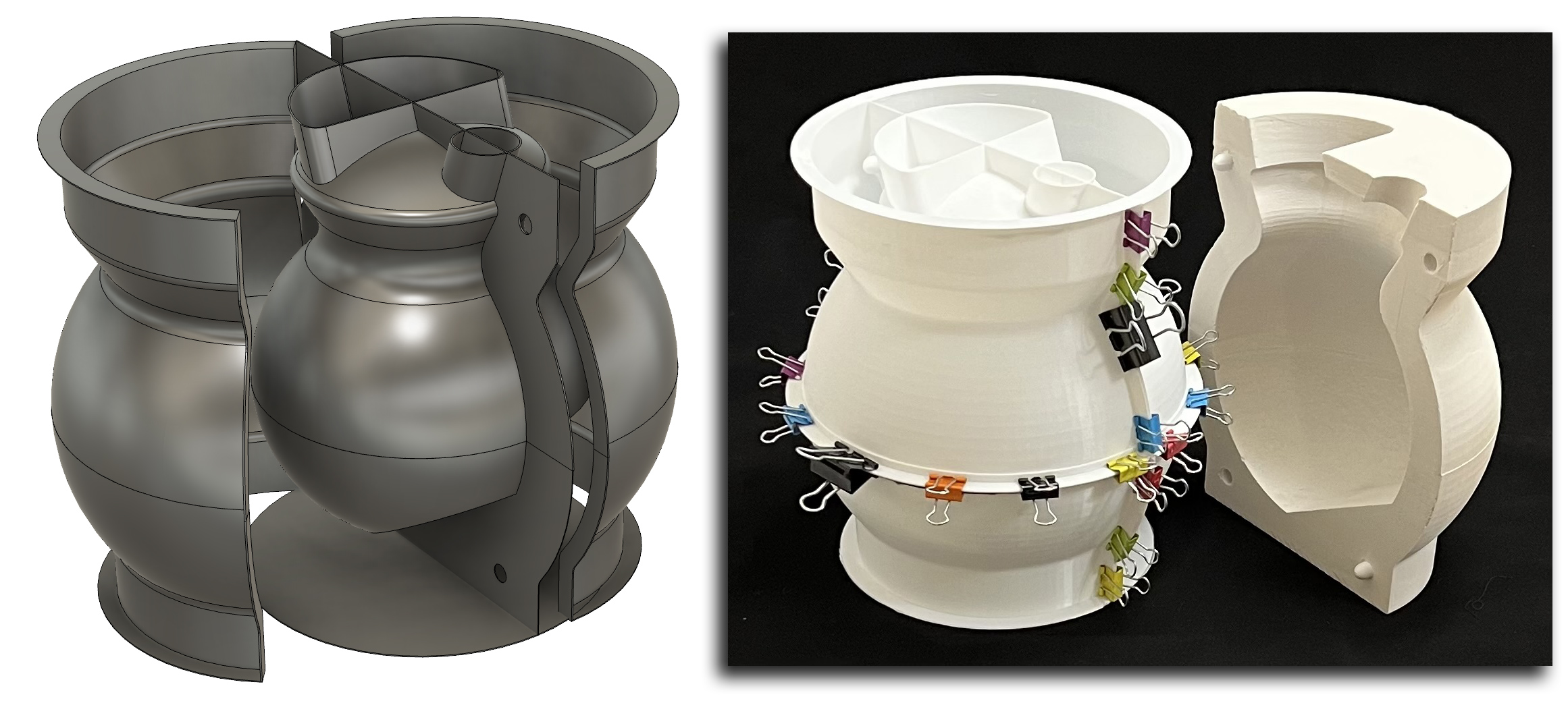
Flanges enable an all-in-one 3D printed block mold for slip casting

This picture has its own page with more detail, click here to see it.
The center piece of this 3D printed assembly defines the outside shape of the ceramic vessel (plus two spares at the top). This entire assembly is an all-in-one case mold for a two-piece plaster working mold. This was printed as six light-weight units on standard Prusa MK3 and MK4 printers, walls are 0.8mm thickness. The upper and lower inside model halves were glued together (with the aid of an inside hoop to line them up). Outer flanges were glued on to enable clamping the outer shell vertically and horizontally.
The membranes defining mold mating points are printed onto the inside model, they extend out far enough to clamp between the flanges of the outer shell sections (suspending the model in the center). The membranes have holes to enable inserting natch-pairs. The thin base is glued on to hold the lower outer shells in place (in flexes enough to enable extracting the plaster form without mold breakage). The whole assembly is held together by clamps so it can be used multiple times.
| By Tony Hansen Follow me on        |  |
Got a Question?
Buy me a coffee and we can talk

https://digitalfire.com, All Rights Reserved
Privacy Policy
