A cereal bowl jigger mold made using 3D printing
Better porosity for Brown Sugar Savers
Build a kiln monitoring device
Celebration Project
Coffee Mug Slip Casting Mold via 3D Printing
Comparing the Melt Fluidity of 16 Frits
Cookie Cutting clay with 3D printed cutters
Evaluating a clay's suitability for use in pottery
Make a mold for 4-gallon stackable calciners
Make Your Own Pyrometric Cones
Make your own sieve shaker to process ceramic slurries
Making a high quality ceramic tile
Making a Plaster Table
Making Bricks
Making our own kiln posts using a hand extruder
Medalta Ball Pitcher Slip Casting Mold via 3D Printing
Medalta Jug Master Mold Development
Mold Natches
Mother Nature's Porcelain - Plainsman 3B
Mug Handle Casting
Nursery plant pot mold via 3D printing
Pie-Crust Mug-Making Method
Plainsman 3D, Mother Nature's Porcelain/Stoneware
Project to Document a Shimpo Jiggering Attachment
Roll, Cut, Pull, Attach Handle-making Method
Slurry Mixing and Dewatering Your Own Clay Body
Testing a New Load of EP Kaolin
Using milk as a glaze
Yixing Teapots
Beer Bottle Master Mold via 3D Printing

The bottle should be doing the talking! Glass bottles are just a container, ceramic bottles elevate beer, they bring sustainability and style to beer drinking. Ceramic bottles bring local craftsmen to your beer experience.
May 2024: Version 4 is even better, natches are working, casting working molds directly from 3D prints.
June 2024: Version 5 now has a separate bottom (three-piece mold) so there is no seam. This enables an embossed logo and variable heights using the same bottom piece.
June 2025: v6 mold is done (for larger format printers, this makes it much easier).
Dec 2025: OnShape version published (enabling one-click open of the drawing itself).
This project is being done to demonstrate the amazing power that 3D printing brings to potters who would like to adopt the slip-casting process for small-scale production.
It is now possible to quickly draw 3D objects on a computer, 3D print block or case molds and have working plaster test molds within a couple of days. The more pieces a mold needs to have the better this system works. It is interesting to note the precision that is possible using this process, and that achieving that precision can be done by simple trial-and-error cycles. Additionally, a potter can create partial or small-scale molds to prototype and then make full-size rubber masters.
Ceramic beer bottles were made historically. They are a very difficult shape for jiggering, needing to be done in two parts and joined. Thus, many companies even had teams of potters making them by hand. For high volume production, slip casting using traditional mold-making techniques was never practical compared to the metal molds used in glass forming. That being said, ceramic bottles have some important advantages over glass - these include decoration and customization options, practicality for potters to make, flexibility to retool size and shapes, flexibility in glazes and colors and options for stamping and embossing. Ceramic glazes, especially stoneware, also have the potential to be more durable. So it is easy to see why we are excited at how easy it now is for potters to take advantage of the ceramic process in ways industry cannot.
This project is long and arduous. I had to make just about every mistake to learn better and better ways of doing things. The best ways are turning out to be the cheapest - using the equipment that I have. My ability to do whatever is needed in 3D design is the single most important key to the continued evolution of the process.
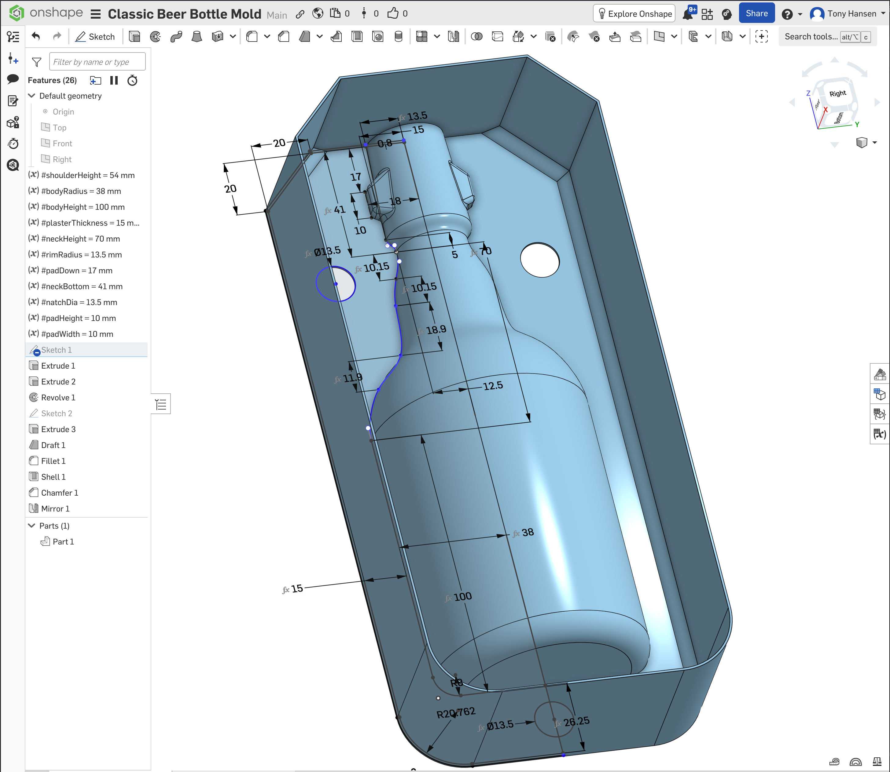
The v6 pictures shows most dimensions. It links to the OnShape drawing, open it for detail on any dimension (and the ability to change them in the variables).
I have included pictures of earlier stages to demonstrate some of the mistakes I made.
Related Information
v6 Beer Bottle Drawing
Fits standard swing top stoppers.
Available on the Downloads page
This picture has its own page with more detail, click here to see it.
3D print this, pour in plaster to make a slip casting mold! My previous work on this project assumed a smaller 3D printer (making it necessary to print flanged PLA mold sections that clip together). But larger 3D printers are now common, making the CAD work much easier. This OnShape drawing is parametric for height, body diameter, wall and plaster thickness, and neck height (for the full bottle set body=160mm, neck=96). This uses my standard natch system. Neck vertices are proportional to height, so resizing works well. The top end is filleted to permit the longest possible mold on the print bed (diagonally). The bottom inside perimeter is chamfered, strengthening the default 0.8mm side wall junction to the base (that being said, be careful not to flex it too much when removing it from the print bed).
Doing this smaller size is for prototyping and testing. Casting plaster on a 3D print creates artifacts; these were not an issue. This PLA mold prints quickly, it has a hollow back side, permitting easy removal with a heat gun. There is no spare, it employs a pour spout, making the mold shorter and producing a better lip.
Need a stoneware slip casting recipe? L4768E or L4768H are a good choice. A glaze recipe? How about GA6-B (or similar)? Go full DIY with this, you will never turn back.
v7 Classic beer bottle mold in OnShape
Make authentic-looking beer bottles that are better than glass
Available on the Downloads page
This picture has its own page with more detail, click here to see it.
The slip casting process is so much more accessible than in the past because of 3D printing. Why not start with this? This bottle has all the same dimensions as my v6 (done in Fusion 360). But, because this is done in OnShape, one click here opens it directly in a browser window with all the power of a professional CAD system. If you have a free account there and are logged in, one more right-click can export it in 3MF or STL format for 3D printing. Or a "Copy Workspace" menu choice will move it to your account to enable editing and setting variables, adjusting the shape, etc. This works in your browser, there is no software to install and OnShape is free for hobbyists. This mold works with my pour spouts (no spare is needed) and natch system (no registration keys are needed). So just insert the clips and embeds, pour in plaster, remove the PLA plastic with a heat gun and you have a working mold. When dry, glue in the natches, attach a spout (using slip) and fill the mold with casting slip.
Need a stoneware slip casting recipe? L4768E or L4768H are a good choice. A glaze recipe? How about GA6-B (or similar)? Go full DIY with this, you will never turn back. Need a guided help to make this happen? Sign up for an Insight-live.com group account and we can work together to make this happen for you.
Slip cast leather-hard full-sized beer bottle prototype

This picture has its own page with more detail, click here to see it.
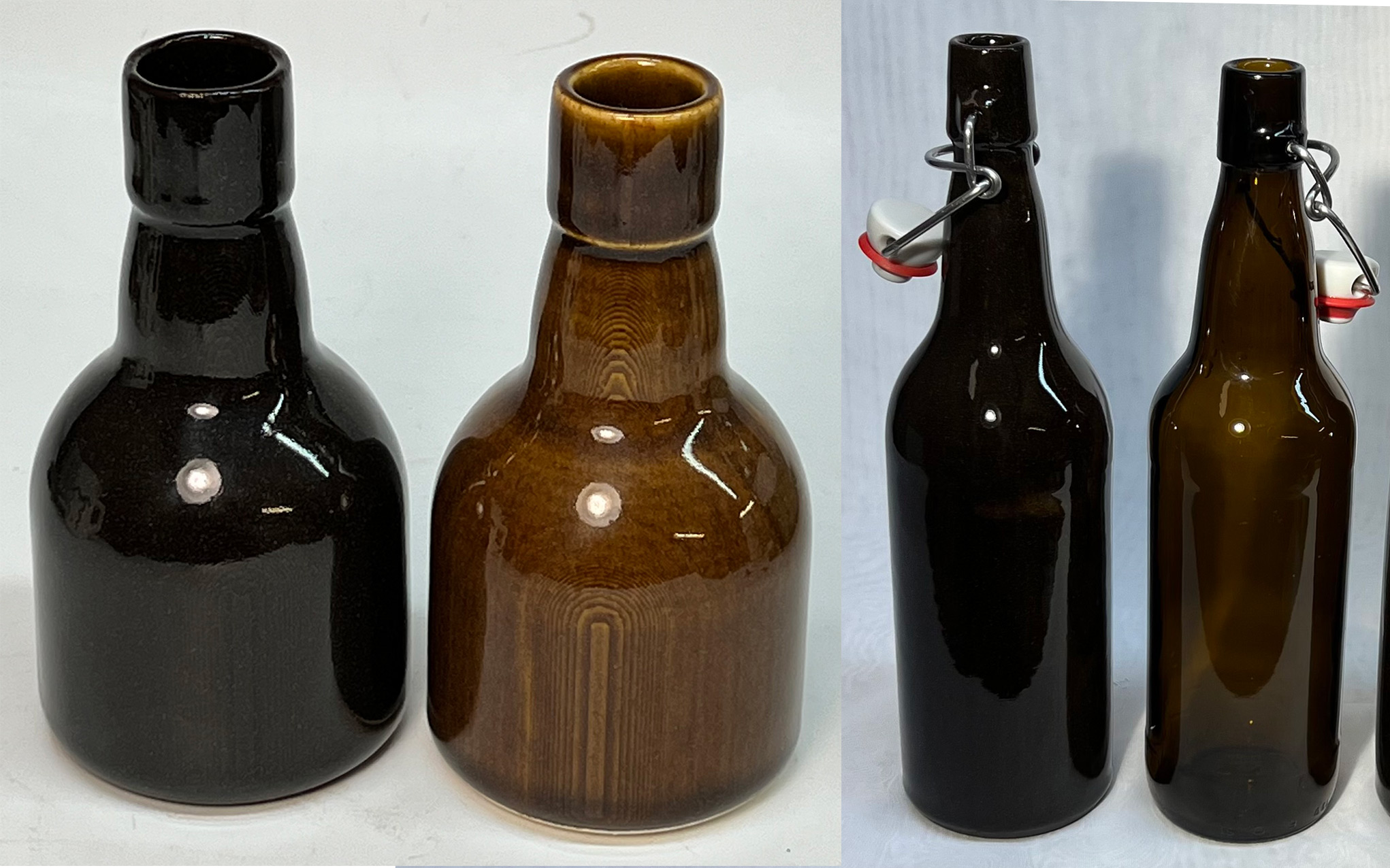
The commercial bottle on the right is 25cm high. These stopper mechanisms are a commodity item, millions are made and a wide range of bottles work with them. They are easy to find online and go by a variety of names (e.g. "Grolsch style flip top stoppers", "Swingtop Grolsch style bottle cages", "Porcelain swing top cap").
The slip cast bottle is on the left - this one is leather hard, recently extracted from a mold. It is made using a black-burning stoneware, the L4768D recipe. As a starting point, I used water/Darvan proptions outlined in the "Casting Recipe" section of the M370 data sheet. By the time this is fired it will be 10% smaller and will match the glass one on the right. The lugs are positioned to work well with swing-top stoppers.
This GA6-B glaze is better than beer bottle glass
This picture has its own page with more detail, click here to see it.
Ceramic glazes, like this GA6-B, are actually just glass. But they are not like bottle glass. The latter is formulated to work well in forming machines (harden quickly), melt and stiffen quickly, have low melt viscosity and resist milkiness and crystallization on solidification. The chemistries to accomplish this have adequate resistance to leaching and adequate durability for a few uses. A stoneware glaze melt needs to be much more viscous (to stay put on vertical surfaces). And, it must have a lower thermal expansion (to match common clay bodies). And, it must resist crystallization much more (since it cools slowly). Fortunately, meeting these needs brings along big benefits: Greater durability, hardness and resistance to leaching. Stoneware glazes and bottle glass share a common trait: They have about the same amount of SiO2. But the similarity ends there, stoneware glazes have:
-High Al2O3. Three to five times more! It is the key oxide for durable glass. And it stiffens the melt (that disqualifies high levels from bottle glass).
-The same fluxes (CaO, MgO, K2O, Na2O). But they distribute very differently (half the CaO, half to one third the KNaO, much more MgO). Other fluxes like SrO, Li2O are also common.
-Low KNaO (which they call R2O). In glazes, it produces crazing, 5% is a typical maximum. But bottle glass can have double or triple that (the high thermal expansion is not an issue, and its cheap source materials supply lots of melting power).
-B2O3 melter. It is expensive but can be justified because the glaze is just a thin layer. Glazes at the low end of the stoneware range have 5% or more boron.
Far right: A glass bottle. Left: Small test bottles made from dark and light burning stonewares. Third: A production ceramic bottle. Notice how much the dark body darkens the GA6-B glaze.
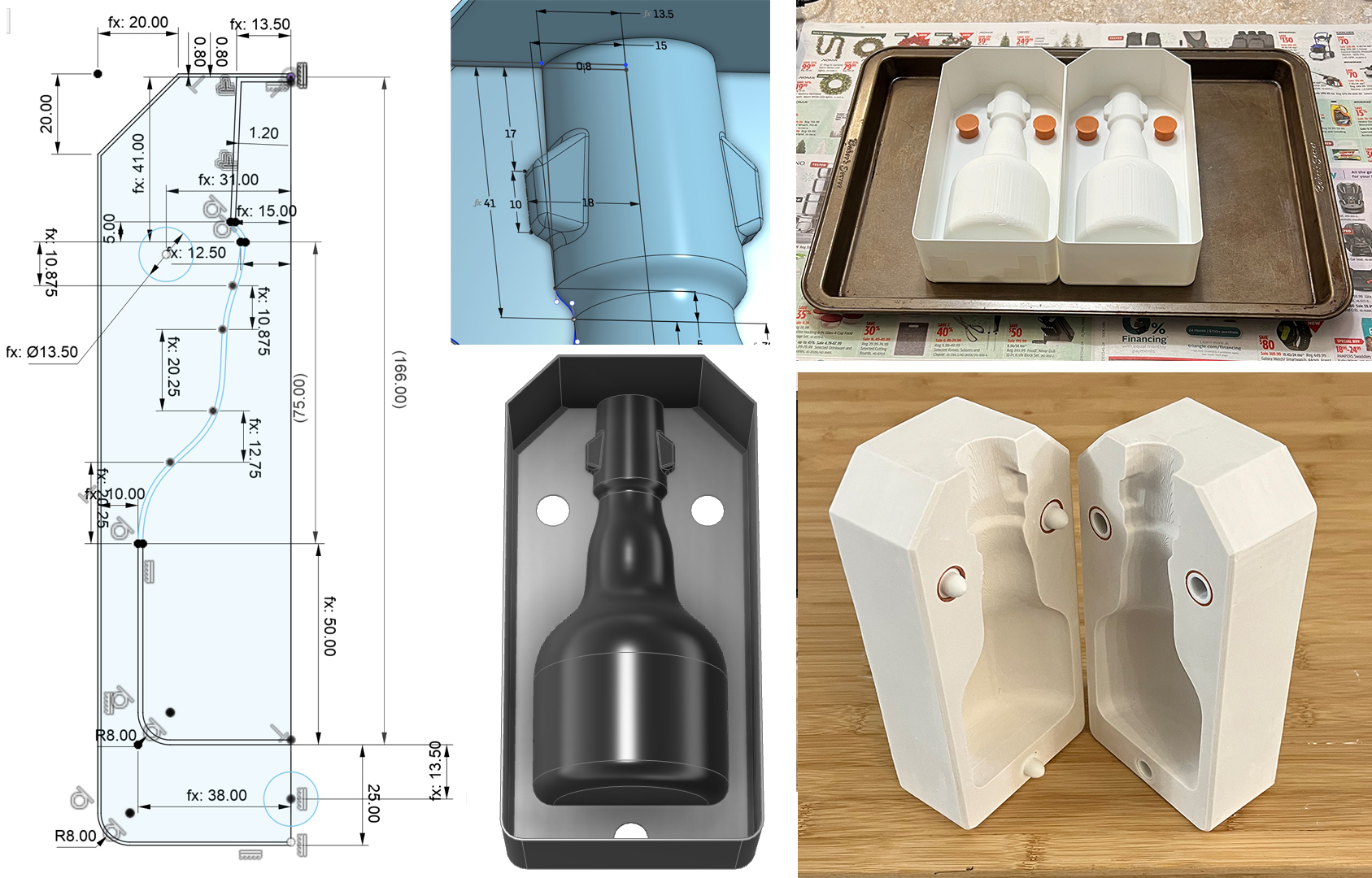
Making a mini bottle prototype mold

This picture has its own page with more detail, click here to see it.
PLA is the most common filament used in consumer 3D printers. Because this is just a quick trial slip-casting mold, it is practical to print two PLA case molds (lower right) with vertical sides (it is impossible to remove the plaster mold from these without significant damage to the corners. But this is not a problem; PLA filament has a very low melting point so even hot water can soften it - I use a heat gun to peel it off. Making these confirms how accurate 3D printers are nowadays - the plaster mold halves mate precisely. Notice there are no natches, they are not needed for prototyping (lining up the outer edges perfectly positions the pieces). And there is no spare; I use a pour spout instead.
A draining issue with a slip cast bottle
It is turning inside out!

This picture has its own page with more detail, click here to see it.
Why did this happen? There is a perfect storm of factors. Draining, during slip casting, creates suction and slip is heavy (1.8 times heavier than water). And this mold is tall with a narrow neck. So that creates a lot of suction. A slip having inadequate fluidity complicates draining. This round shape, even with printing artifacts, also releases well. How can this issue be avoided?
-Draining the mold carefully, holding it near horizontal for much of the drain.
-Use a well-deflocculated slip.
-Add bentonite to the slip, perhaps 0.5%, to make it stickier and slow down release time (which also slows down the casting time).
-At times, this will happen despite all efforts. In that case, if might be necessary to use a tube (e.g. 1/2 or 5/16”) to pump most of the liquid slip out of the bottle before inverting it. Adapt a 3D printed pour spout to keep the tube centered, at least near the mouth of the bottle.
Calibrating the fit for the swing stopper assembly
Three iterations to derive the measurements

This picture has its own page with more detail, click here to see it.
There is no substitute for firing tests pieces to cone 6 to test the fit for the swing assembly. In Fusion 360 I sliced off the top of the bottle and formed a small box around it to be able to quickly 3D print a test case mold of just the upper neck (I cast two plaster mold halves from them). In the freshly cast leather hard pieces, making a hole in the middle of the lug mounts was easy. Although the wire is 2.8mm dia, testing cycles indicated that an 11/64" (4.3mm) drill bit is required. Simply twisting it to create a hole in the center takes seconds. After two more iterations, I ended up with a pad size at 10x10mm and the flat pad surface at 18mm from center. Of course, your casting body may shrink more or less than mine, so be ready to adjust these values.
The link below links to a step-by-step in Fusion 360 of how to save a temporary copy of the mold drawing and modify it to isolate just the top portion of the neck.
How to draw a case mold for slip casting using Fusion 360

This picture has its own page with more detail, click here to see it.
Drawing your objects in CAD software is the most difficult step in leveraging 3D printing for slip-casting. In this 11 minute step-by-step video, we will draw a case mold, using Fusion 360. It can be 3D printed and plaster poured in to make a working mold. Mold soap is not even needed. This method of quickly making a pilot mold is within the reach of almost any potter.
Making the Stopper Holes on a Leather Hard Beer Bottle

This picture has its own page with more detail, click here to see it.
I use an 11/64" drill bit to make the pivot holes in the lugs (at the leather hard stage after extraction from the mold). Of course, they must be centered and deep enough to hold the swing mechanism (but not so deep they punch through the wall). I find that pressing a pea-sized ball of clay into the lugs (inside the neck), held in place by slip, thickens the wall sufficiently. The wall thickness shown here was sufficient to make the holes without thinkening the lugs, but it results in a bottle that is too heavy. If you find a way to automate this process, please let me know.
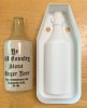
Printing my own version 1 block mold in two pieces

This picture has its own page with more detail, click here to see it.
Of course, this is far too large to print in one piece on my Prusa MK4 printer so I sliced it in two and added flanges to clamp the halves together. There is quite a bit of stair-stepping artifacts on the 3D printed surface, I did not worry about smoothing it and it did not prevent casting two plaster molds. No mold soap was even needed, the plaster molds came out using compressed air. The long side rails did require some stabilization (they were flexing with the weight of the plaster).
Again, this method was only needed because I did not have a printer big enough to print the mold in one piece. Later, I did get one.
Finished cast v1 stoneware beer bottles

This picture has its own page with more detail, click here to see it.
The center bottle is a standard glass one, the other two are ceramic, cast out of my version 1 plaster mold. The stopper fits perfectly. The clay is Plainsman M370 + 10% raw umber, it fires black. The glaze is GA6-B, an amber transparent that produces a deep glass-like effect over the dark burning body. They were fired using the C6DHSC firing schedule. These bottles are a testament to how 3D printing and 3D design now make it possible for even casual potters to make pieces never before practical or even possible.
Version 2 Ceramic Beer Bottle Mold
Making a rubber case master mold

This picture has its own page with more detail, click here to see it.
This time I printed the block mold, rather than the case mold, in six pieces on my consumer 3D printer.
Top: I printed the two halves upright (creating them in the slicer rather than Fusion 360). Because the print lines run concentric the quality is so much better than the previous version printed flat. The ribbing inside made the halves strong so they did not go out of shape when filled with plaster (to give them weight).
Second: The mold halves were simply laid against each other - they mated perfectly (and stayed in place because they are full of plaster). The four rails were then clamped in place.
Third: The PLA was soaped (using Murphy's Oil Soap) and rubber poured in (Smooth-On PMC-746). The next day it easily pulled out.
Fourth: The finished rubber case mold. The sides are pretty flabby so I make them rigid using the four rails (placed upside down).
Right: Using a plaster mold created from this rubber case mold I slip-casted a bottle using my L4768D recipe, glazed it with GA6-B and fired it at cone 6.
v3 Ceramic Beer Bottle Mold Drawing Obsoletes Previous

This picture has its own page with more detail, click here to see it.
Something I love about 3D parametric CAD is how a drawing can evolve to be both simpler and better. While my version 2 drawing had about 20 steps, this one is down to nine. No more ribs, no offsets or mirrors in the sketches, no double-revolves and no seams across the mount ads. Printing will be dramatically faster. The quality of the side rails is now the key factor in final mold accuracy (these stabilize it while filling with plaster from the back).
I now draw the simplest repeatable shape: A one-quarter slice. Step 5 cuts the bottle profile from the solid block extruded in step 4. The preceding steps were a sketch of the bottle and block outline and a plane and sketch for the pad. Steps 6 and 7 are the extrusion and corner rounding of the pad cutout (near the rim). The last two steps mirror this quarter upward to create the block and then shell it to hollow the back side.
The drawing is now fully parametrically resizable, I have taken advantage of that to make a stubby bottle test. Neck spline points are now spaced vertically as a percentage of the neck height parameter - set at "70" here. The body and neck heights are separately set now so the full height is now a driven dimension - it is 146 here.
Pouring the v4 Plaster Beer Bottle Mold

This picture has its own page with more detail, click here to see it.
This project is a testament to my wife's patience with me using her kitchen as a mold-making shop. Most of the tools I need are there. A nice stable table to run two 3D printers, lots of room and plugins, electrical appliances, utensils and supplies of every type, good lighting. And pleasant company!
I have already poured PMC-746 rubber into 3D printed block molds and have printed and put in place stabilizers to hold the rubber in place. Embeds are in place on both the bottle base and bottom mold (upper right). The flexibility of this rubber is amazing, it makes possible extraction of the plaster base, although with difficulty. It also preserves the embossed logo on the foot. This is version 4 (version 5 will have a shallow base piece and modified sliding natches).
The $5 garage sale mixer does not pull bubbles to the surface so I just pull them up by counter-stirring with a serving spoon. A common sense workflow (never pouring any down the sink, cleaning everything in a settling bucket) makes this no problem in the kitchen.
Inbound Photo Links
 Why 3D design and printing is a better way to make slip casting molds |
 The bottle is more important than the beer! |
 Regular bottles of beer looking humble beside the ceramic one |
 Classic Medalta Potteries Beer Bottle Make this mold using OnShape and Fusion 360 |
Links
| Media |
Make a precision plaster mold for slip casting using Fusion 360 and 3D Printing
In 11 minutes you will learn a new way to make complex plaster molds for slip casting - faster and more precise than ever before. Anyone can do this. |
| Media |
3D Print a Test of the Beer Bottle Neck
In 4 minutes you will learn how to modify a copy of the existing drawing to print only a narrower part of the top 8cm |
Video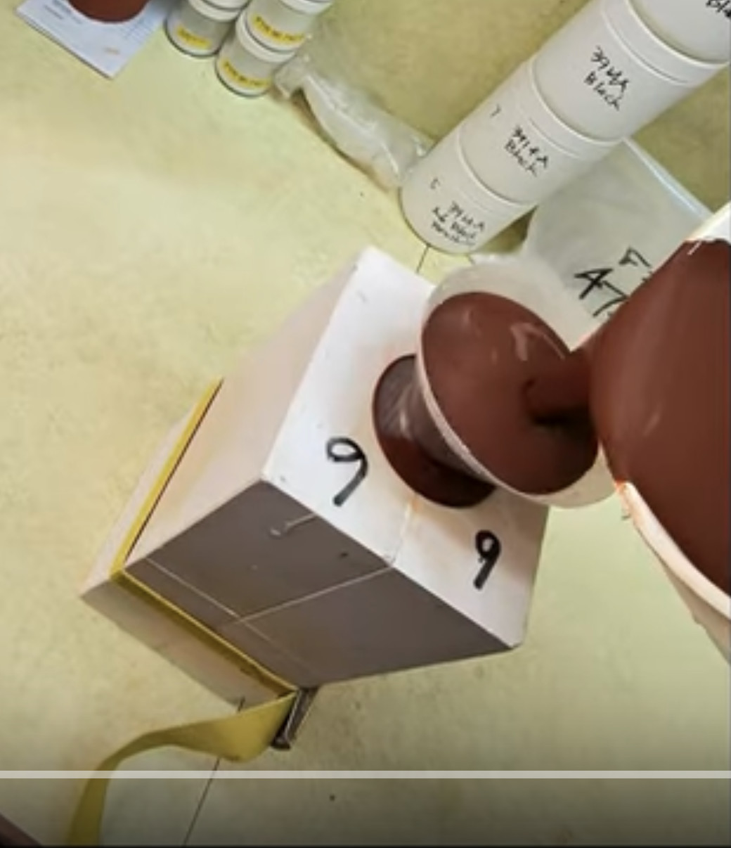 |
Slip cast a stoneware beer bottle
I will mix the slurry, assemble the mold, attach the 3D-printed pour spot, pour in the slip, pour it out, remove the spout, trim the lip, split the mold, extract the bottle and drill the holes for the swing-top stoppers. |
| Media |
Design a Triangular Pottery Plate Block Mold in Fusion 360
Lilly will take you step-by-step through the process of parametrically drawing a triangular plate with curved sides and rounded corners, for 3D printing to pour a plaster working mold. |
| Projects |
Medalta Ball Pitcher Slip Casting Mold via 3D Printing
A project to make a reproduction of a Medalta Potteries piece that was done during the 1940s. This is the smallest of the three sizes they made. |
| Projects | Nursery plant pot mold via 3D printing |
| Glossary |
3D Design
3D Design software is used to create dimensionally accurate objects by sketching 2D geometry and transforming it using tools to rotate, extrude, sweep, etc. The software generates the polygon surface. |
| Typecodes |
Mold making using 3D printing
An ordinary consumer 3D printer has many exciting possibilities for making many types of molds, it is a place where people having both artistic and mechanical abilities can get a double the dopamine! |
 PayPal | No tracking, No ads, No paywall, No transient content! Just organized, concise information constantly updated and improved. Was this helpful? Consider supporting me. |
| By Tony Hansen Follow me on        |  |
Got a Question?
Buy me a coffee and we can talk 

https://digitalfire.com, All Rights Reserved
Privacy Policy