3D Printing a Clay Cookie Cutter-Stamper
A 3-minute Mug with Plainsman Polar Ice
A Broken Glaze Meets Insight-Live and a Magic Material
Accessing Recipes from "Mid-Fire Glazes" book in Insight-Live
Adjusting the Thixotropy of an Engobe for Pottery
Analysing a Crazing, Cutlery-marking Glaze Using Insight-Live
Compare the Chemistry of Recipes Using Insight-Live
Connecting an External Image to Insight-Live Pictures
Converting G1214M Cone 6 transparent glaze to G1214Z matte
Create a Synthetic Feldspar in Insight-Live
Creating a Cone 6 Oil-Spot Overglaze Effect
Design a Triangular Pottery Plate Block Mold in Fusion 360
Designing a Jigger Mold for a Bowl Using Fusion 360 CAD
Downloading and 3D-Printing a 3MF file
Draw a propeller in Fusion 360 for use on an overhead propeller mixer
Drawing a Mug Handle Mold in Fusion 360
Drawing a Mug Mold Using OnShape CAD
Enter a Recipe Into Insight-live
Entering TestData Into Insight-Live
Fine tune the thixotropy of a glaze or engobe slurry
Getting Frustrated With a 55% Gerstley Borate Glaze
How I Developed the G2926B Cone 6 Transparent Base Glaze
How I Formulated G2934 Cone 6 Silky MgO Matte Glaze Using Insight-Live
How to Apply a White Slip to Terra Cotta Ware
How to Paste a Recipe Into Insight-live
Importing Data into Insight-live
Importing Desktop Insight Recipes to Insight-live
Importing Generic CSV Recipe Data into Insight-Live
Insight-Live Meets a Silica Deprived Glaze Recipe
Insight-Live Quick Tour
Liner Glazing a Stoneware Mug
Make a precision plaster mold for slip casting using Fusion 360 and 3D Printing
Making ceramic glaze flow test balls
Making test bars for the SHAB, LDW and DFAC tests
Manually program your kiln or suffer glaze defects!
Mica and Feldspar Mine of MGK Minerals
Predicting Glaze Durability by Chemistry in Insight-Live
Preparing Pictures for Insight-live
Replace Lithium Carbonate With Lithium Frit Using Insight-Live
Replacing 10% Gerstley Borate in a clear glaze
Same Beer Bottle Mold Using Fusion 360 and OnShape CAD
Signing Up at Insight-live.com
Signing-In at Insight-live.com
Slip cast a stoneware beer bottle
Substitute Ferro Frit 3134 For Another Frit
Substituting Custer Feldspar for Another in a Cone 10R Glaze Recipe
Thixotropy and How to Gel a Ceramic Glaze
Use Insight-live to substitute materials in a recipe
Watch Thixotropy Happen With a 20kg Batch of Dipping Glaze
Drawing a Mug Mold Using OnShape CAD
Follow me, step-by-step, as I draw a coffee mug case mold, with handle. You'll be able to 3D print this using PLA filament in a standard consumer printer, pour in plaster to make a working mold. If you are coming from Fusion 360 the process will be familiar.
Click here to watch this at youtube.com or click here to go to our Youtube channel
Transcript/Notes
There are lots of online videos showing the use of 3D printing in creating molds for ceramics. But almost no one shows you how they did it. And they almost certainly do not show a step-by-step of the most complex part: Drawing it in a CAD program. Here, I will do this using OnShape, an industrial strength 3D CAD system that is free for hobbyists. The arrival of such software is an inflection point for ceramic artists and craftsmen, one that is going unnoticed by most.
1
After logging in to OnShape.com, I'll by click on my name on the top right and choose “My Account”, then open the Preferences tab.
In the “Units section” I’ll choose “Millimeter” as the default length unit.
more..
Next, I’ll go back home, by clicking the OnShape logo on the upper left, then click the “Create button”, then choose “Document”, enter a name, and click the blue “Create button”.2
OnShape is parametric, like Fusion three-sixty.
I’ll open the “Variable Table” using this button on the far right.
I’ll need six variables:
For the mug, they are the foot radius of 42mm, base radius of 50, lip radius of 51 and height of 114.
For the 3D print, we need the wall thickness of 0.8mm.
And for the working mold, a plaster thickness of 20mm.
Note that OnShape does not permit spaces in the names.
OnShape exhibits one of its idiosyncrasies here.
You can’t edit the contents of a cell using the mouse.
On each cell, just begin typing to replace what is there. This characteristic is also found in other parts of the user interface, it is a consequence of implementing this in a web browser instead of as an application.
Please pause the video here, if needed, to finish entered the variables.
If you have not already watched our video on understanding the indiosyncrasies of OnShape, compared to Fusion 360, consider doing that now.
3
To start, I’ll hide the front and top planes and then choose the Sketch Tool.
The sketch dialog appears and it is waiting for me to select a sketch plane. I'll click the right plane, and then double-click that face on the View Cube to square it on the screen.
OK, let’s begin drawing the outer profile of the mug.
Choose the line-tool, click on the origin, move rightward to draw the flat foot radius.
Let it infer a horizontal line of about 40.
Draw the diagonal edge of the foot by clicking on a point up, and out, about 10.
Finally, draw wall about 50 high.
Don't let it infer a vertical line, click to get an inward slope.
Then press Escape.
Now, press the “d” key to select the dimension tool.
Click on the first line, pull out a dimension arrow, and click again.
Type “foot radius”, as soon as foot radius is the only item in the list, press the enter key twice.
Now, making sure the dimension tool is still active, click the diagonal point.
Then click the origin.
OnShape guesses whether we want a vertical, horizontal or diagonal measurement.
Just move around until you get what you want. We want this 10mm vertically up from the origin.
Then, I’ll dimension the point to be right of the origin by the “base radius” variable.
Then, I'll move those measurements out of the way.
Notice the line has turned from blue to black. That’s good, it means it is fully defined.
Now, let's repeat by dimensioning that top point
Vertically up from the origin “height times 0.78” mm.
And horizontally right of it “lip radius times 0.88”.
4
OnShape exited that sketch, so I'll right click it and edit it again.
First, I’ll draw a horizontal line for the lip of the mug.
I'll put it about 20 above the endpoint of that vertical side.
I’ll dimension its length as the “lip radius” variable minus four. To do this I have to enter the parameter in the normal manner, then add the "minus four" after. But I also have to finish with "times 1 mm", this is a requirement when added or subtracting numbers from variables.
Next, I'll dimension the left enpoint distance up from the origin as the “height” parameter.
Finally, I’ll choose the “vertical constraint” tool, and then position the left point of the line vertical to the origin.
Next I’ll choose the “point tool” and create a point down from, and to the right of, the right end of the line.
I dimension it 4mm right, and 4.5mm down.
Then, I’ll use the “spline curve” tool to join the lip and the sidewall, clicking on each point and double clicking to terminate at the end.
Next, I’ll use the “Tangent tool” to smooth the transition from curve to straight at both ends of the spline.
For each I'll click the curve (not the curve handle), then the straight line.
To finish the mug profile, I’ll fillet the two corners at the base, to a 5mm radius.
5
Now, let's turn off the "right plane", and offset this profile inward by the “wall thickness” variable.
I’ll do that using the “offset tool”.
I'll carefully click each segment of the mug outline, then use the arrow to get it approximately right.
Finally, I’ll press enter, then type in the "wall thickness" parameter name, and press Enter again.
Now, I’ll create a vertical line, from the origin, up the center, extending above the top line by 10mm.
The reason for this is not obvious, but you will see why shortly.
Next, I’ll choose the “Mirror Tool”.
Notice that its dialog wants me to select the mirror line first, then the entities to be reflected.
I’ll just choose the vertical wall section of the mug, but not the base or lip.
Notice the line sections don't stay selected, but they do accumulate on the left.
I’ll finish with the “construction line” tool.
I'll search for it here. Notice that as I type, it highlights, in yellow, the toolbar item it thinks I want.
And, it gives me a list with descriptions and shortcuts.
This is a great way to learn the locations of the tools.
I'll click the first section.
This doesn't look good. Sometimes it is better not to worry about why this happens.
Just undo, and do it another way.
I'll make a selection rectangle around it instead and then click the construction line tool.
I want the reflected contour to be a construction line because it is only needed as a drawing guide later in the process.
6
Next, let’s create three points to describe the handle.
I'll put them in their approximate positions.
I'll dimension the first to be right of origin by “lip radius times 0.7”.
As a reminder, I am going to all of this trouble with parameters so the mug will scale intelligently if I change one of the variables.
Now, I'll dimension this point, up from origin, about three quarters of the height, namely, “height times 0.77”.
The second point is to the right of the origin by “base radius times 1.44”, this is the outer extremity of the handle, well outside the mug body. As I do this, the dimension lines can get cluttered, but that is not a problem, I can move them out of the way later.
I'll position this second point, up from the origin, about two thirds the height of the mug, the "height parameter" times 0.66.
Now, I'll dimension the third point to be, right of the origin, by the “lip radius parameter" times 0.86.
To finish, I'll position it up from the origin by “height times 0.25”.
Next, let's join the points using the spline-tool. This will give us a curve that has a handle at each end, to enable manipulating the direction of the line out of the point, as well as the pull of its gravity.
Finally, I'll adjust the upper part of the curve, using the handle on the starting end of the spline.
7
Next, using the "line tool", let’s draw the outer perimeter of the mold.
I’ll start from the top end of the center vertical.
Then I'll go leftward, drawing line segments to follow the approximate shape of the mug.
For a piece having no handle and no flared lip this is simple.
But in this case, I have estimate the distance to end up with an approximate average thickness of 20mm, that is what we defined the 'plaster thickness' variable as.
Next, I'll dimension the mold base as that same distance away from the foot of the mug.
I can then use that as a visual guide to fine tune the positions of the vertexes that join all the lines that form the perimeter.
Next, I'll add three 13.5mm natch holes.
To do that, I'll use the "center point circle" tool, click for the position, drag the approximate diameter and release the mouse button, enter the diameter, and press the Enter key.
Then I'll press Escape to leave that tool, select it, press command-C for copy, then command-V twice to paste. If you are using Windows that will be control-C and control-V.
Next, I'll position each of them.
Finally, I’ll fillet the corners.
8
Now, let's save the sketch we have been working on and create another for the oval cross-section of the handle.
But we need a plane to sketch on. So I’ll search the “Plane tool” and select it.
I'll choose the “Curve Point” option in its dialog, then click the top end vertex of the handle and the curve itself (notice these clicks enumerate in the entities box).
Finally, I'll confirm. We now have a plane perpendicular to the handle curve, at its top vertex.
I'll click the sketch tool and then click on this new plane.
Then, I'll rotate from home and zoom in. I need to be able to recognize OnShape's horizontal inference when I draw the oval, and, I also need to be able to see the top vertex point.
I'll find the "ellipse tool", click on the point, and drag rightward.
Notice that OnShape is prompting me to go horizontal.
I will click twice to set the approximate width and height.
It will then offer fields to enter a width of 20 and a height of 12, I'll press Enter after each.
Next, I’ll offset the oval inward by the “wall thickness” parameter.
Then, click the green checkmark to finish the sketch.
9
I’ll go home by double-clicking the right-front spot on the view cube.
Notice I have renamed these as "main sketch", "handle plane", and "handle sketch".
I did that by right-clicking on each, and choosing the "rename option".
Next, I'll hide the handle sketch and its plane.
Now, I’ll select everything and use the "extrude tool".
I'll pull backward by “lip radius” plus “plaster thickness”.
I'll click OK when done.
This creates the outside shape of the mold.
From now on, we will be cutting shapes into this block, both back and front.
Now, let’s sweep the handle and subtract it from the block.
I’ll make the main and handle sketches visible,
find the “sweep tool”,
and select the inner oval as the face.
As you can see, that gets added the the "faces and regions box in the sweep dialog.
Now, I'll click the "sweep path" box in the dialog and then click the handle path.
I’ll make sure the “Remove operation” is selected.
Then I'll click the green checkmark.
The handle has now been carved out of the block.
We're finally working in 3D!
10
Next, we want to carve the mug profile out of the block.
I'll do that using the revolve tool. It is over here on the left.
It's dialog prompts me to choose the faces to revolve.
And then the axis.
I'll choose to remove, rather than add, material.
Notice, I've forgotten to draw the spare on the main sketch.
And, there is an issue with the lower handle-join right here.
The timeline enables fixing issues like this.
I can go back and and edit the original sketch.
Let's do that.
I'll right-click to edit the main sketch.
11
I'll draw a diagonal line upward.
From the point at the lip edge.
To the top of the mold.
I'll dimension the line at 25 degrees from vertical.
Then, I'll choose the line tool.
Then, draw a small connector downward from the same point,
following the same 25-degree angle (which it should infer because I hovered over the line).
Next, let's look closer at the lower handle vertex.
I need to move that inward a couple of millimeters.
So, I'll double-click the dimension and reduce the ratio from 0.86 to 0.85
Let’s also adjust the curve coming out of the point.
Adding these two new lines affects actions done later, both the extrude and revolve.
First, let's fix the extrude of the block.
I'll edit that to include the two new areas defined by these two lines.
Now, I'll edit that last revolve to include the same two faces.
Now, we are getting a very good-looking result.
12
Let's turn off the sketch to get an unobstructed view.
And zoom in on where the handle joins the mug body.
First, I'll find the fillet-tool.
And use it to round the joins by 3mm.
Then, let’s turn the whole thing over and find the "shell-tool".
It's dialog prompts me about which faces to remove.
And then for the shell thickness.
I'll set that at the “wall thickness” parameter.
We now have a cavity into which plaster can be poured to make half of a working mold.
We are ready to 3D print this.
Although I could mirror this here, it is not needed.
The 3D slicer software can reflect it across the flat face to produce the other half.
13
Next, I'll edit the main drawing again to draw the pouring-spout-slash-cutting guide.
Above the mug, I’ll create a corner rectangle 1.2mm wide and 20mm high.
To dimension as I draw, the sequence is: click, drag, click, “1.2”, enter, "20", enter.
I'll press Escape to exit that tool.
Then, hover over the corner lines until I find the perpendicular constraint that OnShape automatically inferred.
I'll click on it and remove it.
Notice I can now move the bottom independently from the top.
Now, let’s set the angle at 25 degrees using the dimension tool.
The sequence is to click the line, click the vertical center line, position the number, click, “25”, enter.
Now, using the line tool, I’ll create a 2.5mm wide step.
I'll be careful not to infer it at the center.
Then, a vertical line back up to the spout wall.
Then I’ll vertical-dimension the step 8.5mm up from the base.
I am drawing the step like this so the spout can be printed upside down without supports.
Theoretically, I would constrain the seat of the spout vertically above where it fits.
But, I have found that dimensioning its diameter is better.
A poor fit is then just a dimension-change and reprint away.
I'll set it at 50.16 from the center.
Finally, I'll finish the sketch and use the revolve tool to take this into 3D.
14
There are two more quick things to do here.
First, I’ll extrude the three natch-holes to cut them out of the shell.
Of course, being able to select these depends on the main drawing being visible.
I'll then use the arrow to move them backward, then choose the remove operation, and click OK.
Next, I’ll chamfer the inner edge by 3mm.
This chamfer serves two purposes.
It strengthens the corner for this thin-walled mold.
And, it enables easier splitting of the working mold.
Let's turn off the sketches and admire what we just made.
I hope you are as amazed as I am that such a complex drawing can be done in so few simple steps.
And how practical this method is for making slip casting molds for ceramics.
Links
| Typecodes |
Mold making using 3D printing
An ordinary consumer 3D printer has many exciting possibilities for making many types of molds, it is a place where people having both artistic and mechanical abilities can get a double the dopamine! |
v3 Shelled AI Mug Using OnShape CAD
A great on-ramp to learning slip casting
Available on the Downloads page
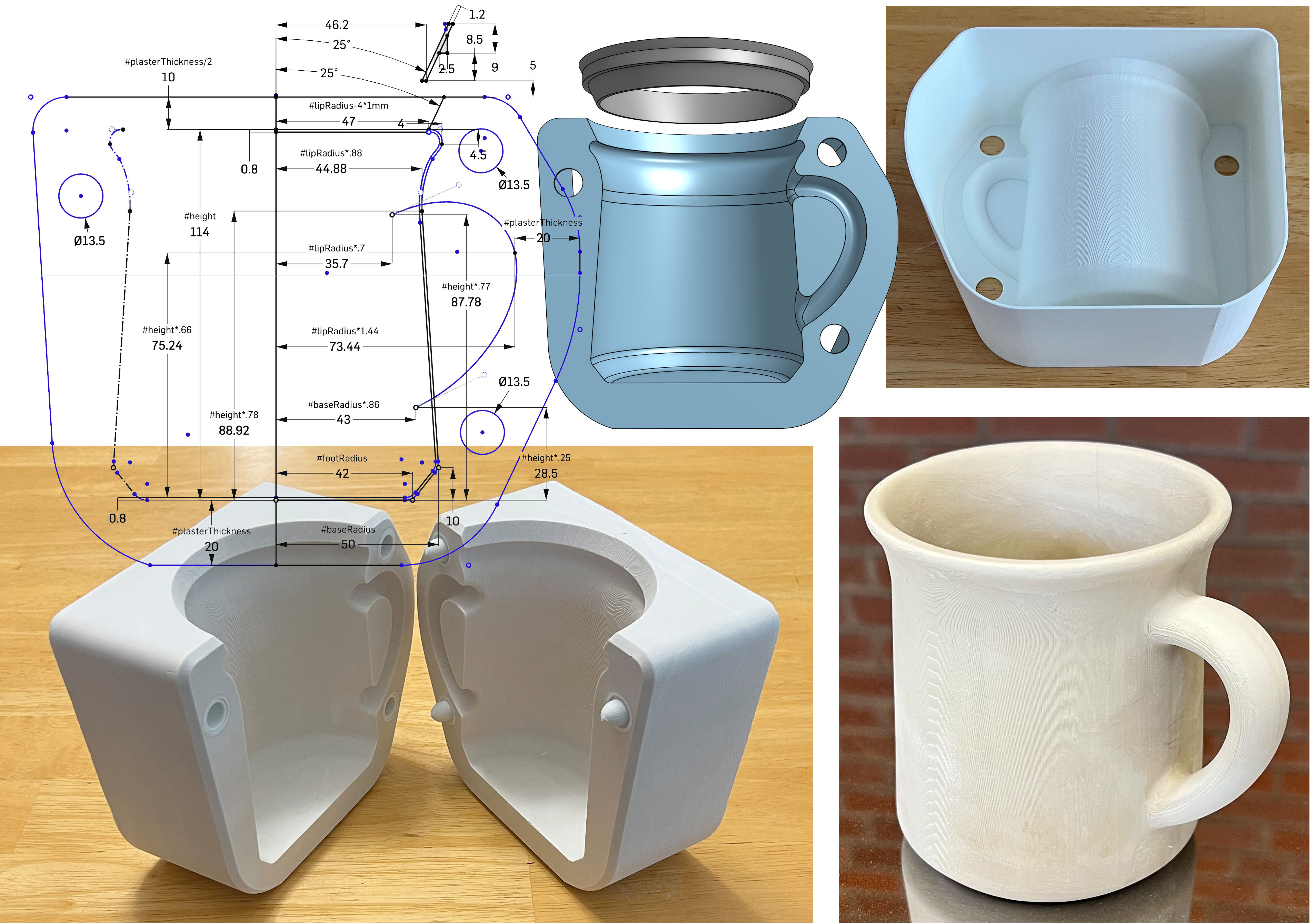
This picture has its own page with more detail, click here to see it.
Follow the video, step-by-step, to create this yourself. Don’t expect perfection the first pour, we did this dozens of times to get to this point. You’ll still make a few mistakes before getting it right, that is what DIY is about.
This design differs from the v2 drawing in that the plaster pouring cavity is formed by shelling (hollowing) the back side (top right). And this is designed for removal using a heat gun. This method has several advantages:
-No sketch offset or extrusion was needed to make the outer wall.
-Because the first 3D action is to extrude everything as one solid mass, corners of the outer 3D perimeter can be chamfered (but don’t do it so much that that there is insufficient thickness for the natches).
-The mug's geometry (offset inward by 0.8mm) is revolved, swept and bevelled by cutting into the block. Shelling to the same 0.8mm wall thickness, from the backside of the block, produces the cavity needed (top right).
-The last steps, after shelling, are chamfering the outside inner corner, cutting the holes for the natches and revolving the pouring spout (as a separate body).
-Our v3 natch system continues to work well with this (lower left).
-Printing artifacts are not a problem for prototype molds (visible op right). Production is asking me to enhance these (a freshly cast mug is shown lower right).
-The plaster mold is of stunning quality (the PLA 3D print was softened using a heat gun and carefully removed using needle-nose pliers).
-Slip cast mugs most often have poor-quality and oval lips. This one stays round because of the outward flare and the quality is better because the 3D printed pouring spout also acts as a cutting guide at the pre-removal stage.
-The PLA pouring spout is deep and absorbs no water. Thus, the slip level does not need to be topped up during casting, the slip surface stays flatter (not developing a bowl shape) so pour-out time can be accurately gauged by its slip level.
There are many casting body recipes that would work with this. DIY CAD skills will enable you to follow me into another exciting world: Low-cost 3D printing of the clay itself! Coming soon.
 PayPal | No tracking, No ads, No paywall, No transient content! Just organized, concise information constantly updated and improved. Was this helpful? Consider supporting me. |
| By Tony Hansen Follow me on        |  |
Got a Question?
Buy me a coffee and we can talk 

https://digitalfire.com, All Rights Reserved
Privacy Policy