2022: This book on reduction kiln design for pottery was written in the 1970s. Over the years many potters referred to this when designing their own kilns. The author, Jim Clachrie, was an expert in gas burner design (he worked at Canadian Western Natural Gas). Thus, although this book outlines many principles of kiln design, it is most authoritative on the technical aspects of burners. Burners based on Jim's design were sold by Plainsman Clays for almost 50 years. We are part way through converting the book originals to web and PDF format. We plan to convert the drawings to vector and 3D. If you are able to assist with this project please contact Tony Hansen.
Jim Clachrie also contributed to a book on pottery kiln design by MARTIN HALSTEAD PLACE
.
![]()
J. R. (JIM) CLACHRIE
Why in the world would a person who is not even a potter have the nerve to write a book on kiln building when there are several good books out written by some of North Americas best known potters?
One reason would be that numerous excellent books available written by outstanding potters are exceptionally good for learning the history and basic knowledge of North American and Overseas kilns and with them an experienced potter would probably have little trouble building a kiln. However, what appears to be needed is a book with the simple basis, the "Nitty gritty" of where to place what brick.
Another reason could be that after 30 years of designing gas-fired industrial equipment, it is easy to look at a kiln for what it is, a simple gas-burning appliance. While some potters may believe there is, a mystique, understood only by a few; people experienced in the design of industrial gas equipment consider a kiln just another very basic gas-burning device. By comparison with today’s sophisticated industrial furnaces and equipment used by many processors, foundries, and metal fabricators, it is the utmost in basic simplicity.
However, in its simplicity it is still necessary to plan the kiln properly to be able to fulfil the potter's wishes for top quality firings with the desired atmosphere, in safety, and with as reasonable efficiency as possible.
With these facts in mind, there appears to be a place for a "Nitty Gritty Gas Kiln Book".
Experienced potters and kiln builders, a please forgive me, but this book is specifically aimed at the people who need the most help, and that is the area where the least help has been available in the past.
This was brought home to me very suddenly one time at the start of a course on kiln building. When asking each participant to give their name and pottery experience, I suddenly discovered that 5 men in the
I must admit to being an old fashioned traditionalist and not a gambler. If a kiln is of a well proven design and there is no gamble involved, that's the kiln I recommend. In most cases, that means a brick down-draft kiln of proven proportions.
We have seen people copy large factory built kilns with unhappy results. Factory-built kilns are often a compromise between performance and portability so why risk the performance if you don't need the portability.
There are several designs available for kilns which are neither up-draft of down-draft. The burners and vent outlet are both near the bottom but there is no bag wall. You get more space per dollar but is there really a saving if you sacrifice good, reliable, repeatable performance.
Our tests on scores of kilns over many years has proven that the potters with the most consistent performance and the most even temperature from top to bottom and side to side were firing with traditional down-draft kilns.
A word of caution may be wise at this point. Some potters have found how to correct for, live with, and get good results from a poor kiln. They have learned how to place wares or otherwise correct for the faults of a poorly proportioned kiln.
In one city there is an instructor with a terrible kiln which they have learned how to correct for and sincerely believe the kiln is wonderful. As a result, they recommend the kiln to their students and the result is often disastrous. No matter what type of material is used in construction, the use of well proven designs of traditional kilns removes the gamble and assures success.
It is our hope to herein present a simple, understandable book which will start at the basics of combustion, inspections, materials, burners, kiln proportions, and conclude with some easy to follow kiln plans which have proven successful.
Combustion is defined at the rapid oxidation of a fuel for whenever we burn a fuel we combine it with Oxygen. First let's discuss the necessary ingredients.
Air is approximately 20% Oxygen (O2) and 80% Nitrogen (N2). The Oxygen is need in the combustion process but the 80% Nitrogen must be heated and the passed out the vent and reduces the efficiency.
Natural Gas (Methane CH4) and Propane (C2H6) are °F (849°C) the combustion or oxidation process will begin.
Since the combustion process for Methane and Propane is basically the same, we will for simplicity deal only with the combustion of Methane (Natural Gas).
Symbols:
Oxygen - O2
Nitrogen - N2
Carbon Dioxide - CO2
Carbon Monoxide - CO
Water - H2O
Methane - CH4
Ignoring the N2 which is inert, the formula for complete combustion will be:
CH4 + 2O2 = CO2 + 2H2O + Heat
Methane + 2 Oxygen = Carbon Dioxide + 2 Water Vapour + Heat
Note that all of the carbon has combined with the oxygen to form the harmless gas, carbon dioxide. The above perfect or complete combustion can only be achieved by specialized equipment. In actual practice a surplus of oxygen is present, some of which is not used in the combustion process and is passed through as part of the flue products, as in the formula:
CH4+ 3O2 = CO2 + 2O2 + 2H2O + Heat
Gas + Oxygen = Carbon Dioxide + Oxygen + Water Vapour + Heat
If the amount of oxygen is restricted as for a reduction firing, the formula, oversimplified will be approximately:
CH4 + O2 = CO2 + CO + H2O + Heat
If the amount of air or oxygen is reduced even further there may not be enough oxygen to transform all the carbon to CO2 or CO and some will remain as free carbon to blacken the kiln and sometimes the studio. Over reduction is a very common fault in many firings.
To relate all this to the kiln; there are 3 ways to create the desired oxidation or reduction atmosphere in the kiln.
An understanding of some terms and exactly what happens as the damper is closed, and its effect on the combustion atmosphere, will help under-stand much of the preceding material.
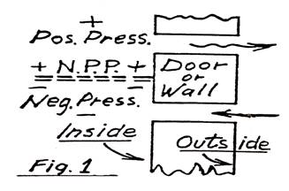
Positive Pressure Zone: This is any area in the kiln where the atmospheric pressure is above normal. During a reduction firing this would extend from the damper back to just be-low the floor. In a poorly designed kiln, or over-reduction, it could extend to below the top of the burner ports and cause flue products to back out the burner ports.
Negative Pressure Zone: This could be the whole inside during the oxidizing fire but is normally downwards from just above the top of the burner port and all the chimney and vent connector downstream of the damper.
Neutral Pressure Point (N.P.P.): Although very important, this is probably the least understood. It is in the area or line above which is positive pressure and below which is negative pressure. The N.P.P. moves up and down according to the damper setting and chimney draft due to chimney temperature and height. Its position can easily be positioned if there are peep holes in the right location. Air, smoke, or a match flame will be drawn in below the N.P.P. but hot flue gases or flame will discharge from above the N.P.P. as follows.
N.P.P. during a reduction firing
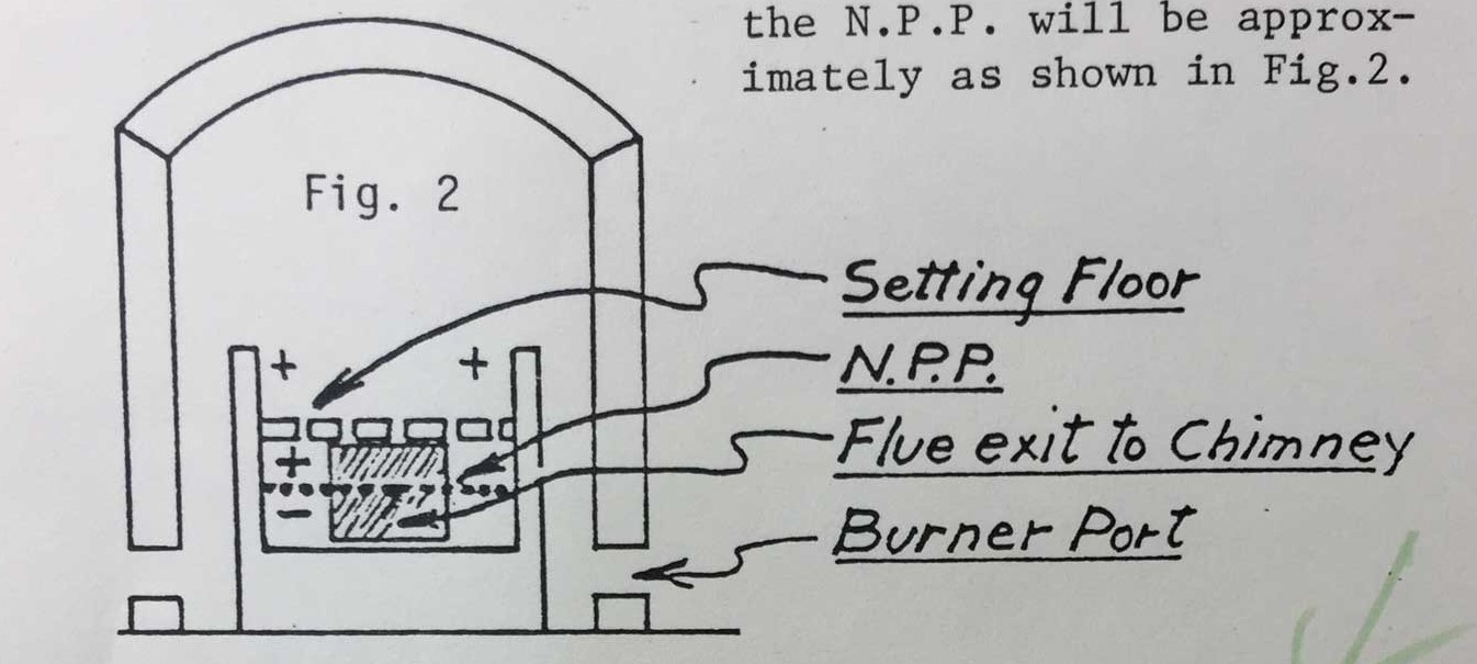
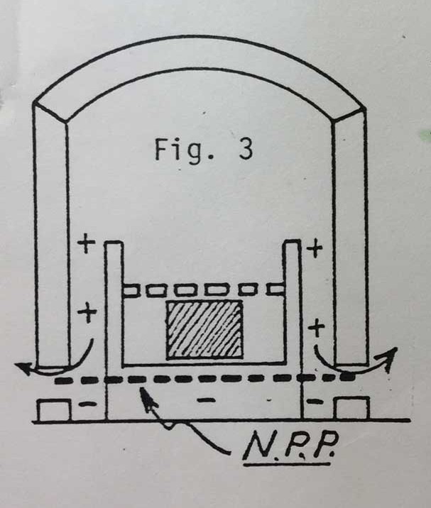
If we close the damper too far the neutral pressure point can move downwards till it is below the top of the burner ports so flue products laden with carbon monoxide will vent from the burner ports. If the kiln is designed with the vent outlet too low in relation to the burner port the problem would be increased.
You will note that in several places in this book, cooperation with the Gas Inspection authorities is mentioned.
It cannot be stressed too much that Inspection Authorities are in existence for our safety and the protection of our lives and property.
In most areas the gas installation must be done by a licensed Gas Fitter who must take out a permit. In some areas the home owner must take out a "home owner permit" which allows him to do his own installation on his own property. The installation will be inspected on completion.
It is my recommendation to go see the Gas Inspection Authorities before starting construction. They may have regulations which specifically apply to kilns or they may not. Where there are no regulations, it is often found that inspectors tend to be more cautious and his is understandable in view of the responsibility they incur in approving an installation.
Following are regulations which are in effect in some areas and are good, logical rules. Where there are no regulations specifically written for kilns, it would be wise to follow them as guidelines. We suggest that these be shown to Inspection Authorities in such cases and they will know you are interested in having a good, safe gas installation.
In the Chapters "A place for the Gas Kiln" and in "Propane in Kilns" are mentioned other regulations which apply to kiln installations in residential areas and the use of propane.
Again we would emphasize; see the Inspection Authorities before starting construction, show a willingness to co-operate and you will find them co-operative and helpful.
Personal observation over the last several years had led me to believe that some potters consider themselves and their families to be fireproof and immune to the effects of carbon monoxide.
In a time when all appliances (gas, oil and electric) must be certified by the Canadian Association, Canadian Standards Association, or U.L. of Canada, we as potters must consider ourselves fortunate to be able to build our own kilns. Asphyxiation or more fires could result in the inspection authorities considering it necessary to change this situation.
At present, in most provinces, a special inspection or operational test is required on all gas units over 400,000 BTU and on all unapproved gas appliances of any input. This must be requested by the gas-fitter.
In most areas the gas installation must be made by a licensed gas-fitter who must take out a permit. In some areas the home owner may take out a “home owner permit" which allows him to do his own gas installation which will be inspected on completion. Be sure to check the regulations in your area.
Remember, the gas inspection authorities are there for our protection and it is for our own safety and to our own advantage to cooperate.
Now, let's look at safety for potters and their families (or survivors) from the three aspects of:
As a start, we'll consider the properties of this villain: Carbon monoxide. CO is a gas - odorless, tasteless and slightly lighter than air. It is a product of incomplete combustion and is not present in detectable quantities in gas appliances properly designed and operated such as your water heater, range or furnace. However, when some factor such as over firing, or smothering caused by scale, carbon, damper, obstruction, or the lack of sufficient combustion air (oxygen), interferes with the complete combustion, CO is generated. Complete combustion of natural gas is shown in the formula:
CH4 + 2O2 = CO2 + 2H2O + Heat
With incomplete combustion, all of the carbon and oxygen have not united to form CO2 but because of the lack of oxygen, it has remained as CO. Many applied producing CO are not detected because all of the flue products are being vented to atmosphere. When the CO is combined with improper venting there is a hazardous situation. It is somewhat fortunate that although CO is odourless, it is usually accompanied by a pungent, biting, eye-stinging odour grouped as "aldehydes". Unfortunately, our blood has about forty times the affinity for absorbing CO than it has for O2. Its effect is accumulative and small quantities received over an extended period do cause blood-related problems and brain damage and can eventually result in death.
And still, many potters ignore the simple and effective safety precautions and in some cases have had to be forced to protect themselves. The writer has personally taken carbon monoxide tests in three potters' workshops where CO was present in hazardous quantities. CO in the air of over .01% (100 parts per million - p.p.m.) is considered by the authorities as hazardous. Headaches can be caused by .02%
(200 p.p.m.) and death by .04% (400 p.p.m.). The CO detector we use can detect down to .001% or 1/1000 of one percent or 10 p.p.m. My wife, who is an Electroencephalograph Technician, has recorded the results of brain damage as a result of day-to-day exposure to carbon monoxide accumulated during working hours. During the course of twenty-five years in the gas industry, I have investigated scores of fume sickness cases and numerous fatalities. Without exception, everyone was the result of someone's ignorance, carelessness or lack of simple precaution on the part of the manufacturer, installer, occupant or victim. All could have been avoided.Now, let's get down to brass tacks and look at how common sense and a few precautions can eliminate the problem.
Most potters do reduction firings. In this the damper is partially closed and/or the air inlet reduced to cause a smothering atmosphere and the result is CO produced in quantities well above the range of our detectors. All kilns leak some when they are hot so there is seldom 100% venting to the outside. To be safe, we must attempt 100% venting and eliminate exposure to any leakage which cannot be prevented.
Kiln Design
Kiln Location
(a) The Chimney
Of the three kiln related fires I am aware of, two were caused by the proximity of combustible material to the chimney.
There are no regulations as yet, as far as I know, written specifically for kilns. The most similar unit covered by regulations is the incinerator and its vents.
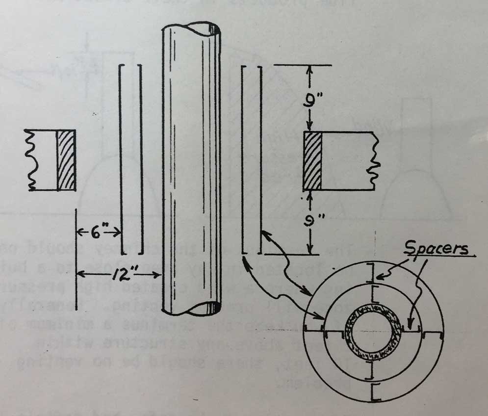
Clause 6.2.8.6 (9) of the National Building Code states: "Except as provided in sentence (10), every interior metal chimney shall have a clearance of at least 3 feet to combustible material within the storey in which the heating appliance is contained." Sentence (10) states: "Where a metal chimney passes through a combustible roof
assembly, the clearance between the chimney and the nearest combustible material may be reduced to 12 inches provided the metal chimney is guarded by a metal thimble extending at least 9 inches above and 9 inches below the roof construction. Such thimbles shall have double cylindrical walls with a ventilated space between the walls and between the metal chimney and thimble, and the clearance between the metal thimble and the combustible material shall be at least 6 inches." The preceding sketch may make this a little clearer.Regarding clearances for brick chimneys, I can find nothing in existing codes which apply and would therefore recommend that this be discussed with the enforcing authorities in your area. It is generally accepted throughout the gas industry that no combustible material should be, permitted to reach a temperature in excess of 45'C (117 F) above ambient. The onus is on you as a potter to see that these temperatures are not exceeded and should be checked on your first firing. It is vital to remember that the temperature of the outside wall of the kiln and chimney continues to rise for some hours after the kiln burners have been turned off.
(b) The Kiln
The clearance between the kiln and combustible material should be at least four feet. This could be reduced if acceptable insulation is provided but in no cases should it be less than two feet to provide for burner access and adjustment. No kiln-caused fires or accidents need happen and they could result in unreasonably harsh regulations being legislated.
Again, remember the outside temperature will climb for some time after the gas has been turned off.
Safety from Explosion
Delayed ignition sounds better for the P. R.
While we are not aware of any problems in this field there is still reason to be on guard.
First, let's look at the properties of the fuels:
| Natural Gas | Propane | |
|---|---|---|
| BTU (British Thermal Units) per cubic foot | 1000 | 2450 |
| Flame Temperature | 3415°F (1879°C) | 3495°F (1924°C) |
| Ignition Temperature | 1202°F (650°C) | 932°F (500°C) |
| Cubic foot of air to burn one cubic foot of gas | 10 | 24 |
| Specific Gravity* | 0.6 | 1.55 |
* In case of a gas leak in a kiln:
Again, no codes are written but there are some general regulations which apply to all
appliances :Automatic safety shut-off must be installed where there is automatic on-off temperature control.
Safety shut-off on propane must shut off both the pilot and the main gas.
It is doubtful if any inspection authority would approve a kiln in a public building without safety shut-off.
We would also strongly urge that safety shut-off be applied on indoor kilns on any burners that are operated unattended.
No burner or pilot should ever be lighted without checking first that all valves are closed - then wait five minutes before lighting.
Although most kilns use atmospheric burners there are a few using small power or forced air burners. On a power burner, an electricity or blower failure can cause flames to come out the fan housing. Codes require an air flow sensing device to cut off gas in the event of air failure. Without such a safety device no power burner should be operated unattended.
In the event of a gas failure, the gas to the kiln can be shut off by either safety pilots or a low gas pressure switch on the pipe. Either one will provide protection in case the gas supply goes off and is later re-established.
Some of the above safety equipment is rather expensive - but then so are funerals.
In closing, let me again point out that inspection authorities and regulations are for our protection.
If you wish specific advice regarding what has been mentioned here, contact the local inspection authorities, the Utilization Department of your Natural Gas Company or the writer.
Don't let safety go to pot!
One of the most often asked questions at schools and workshops is - What type of kiln should I build?
With the cost of kiln building products today and considering the permanency of some kiln constructions, it is worthwhile to spend some time discussing with other potters their opinions on kilns they have used.
This paper may provide more questions and answers but we hope some of the comments will help in making that important decision.
Since the size usually determines the type of kiln, this is probably the first decision. Is the kiln just a hobby or will you eventually sell your wares? Do you wish to do tall sculptures or smaller pots? what floor dimensions do you need? What do you think your needs will be in 2, or 5 years from now? Are you renting the property and do you want to be able to dismantle and take the kiln with you? Will a large kiln require the resizing of the gas service into the property or will the existing service do? Is your lot zoned strictly residential or commercial? What money can I spend on a kiln?
Considering all these, now lets look at the types of kilns and their properties.
If your wares will always be small, if you need a portable kiln, if the gas service cannot provide for too much increase and you're short of money, and if you can live with a cone or more temperature difference from top to bottom, consider a small up-draft kiln.
In dollars per usable ft3 it is certainly the cheapest to build, and there is no large chimney needed. If it is to be indoors, a canopy could be power exhausted out the side wall, but not to a neighbours property or near any windows that open or fresh air intakes.
In size, 10 to 12 usable ft3 is the largest up-draft kiln I would personally consider. In this size about 9" height is needed below the floor as a combustion chamber.
All smaller sizes make it a little more awkward to fit with kiln shelves. A 12 ft3 kiln with a floor 27" x 27" can use four 12" x 12" on each level but on a 6 ft3 kiln it is possible to cast your own kiln shelves.
For those worried about building a sprung arch roof; a kiln 22½" wide can use 2 or 3 square edge tiles 2½" thick x 12" x 24" as the roof. On the smaller sizes also, one of several designs of "portable" roofs could be used. One of this type has the insulating bricks clamped between channel iron while another has the insulating bricks slung on rods placed through holes drilled through the bricks.
The Cross draft Kiln
The cross draft version of a down-draft kiln is well worth considering in the range of 12 to 20 usable ft3 Indeed many potters are happy with their cross draft kilns in sizes much larger than this.
In considering a smaller down-draft kiln firing from both sides, there becomes a point below which the cost per usable ft3 becomes impractical. On each side of the setting floor there is about 8" to 10" of combustion space and bag wall which remains constant no matter how small the floor is. For
this reason it becomes logical in the smaller sizes to do away with the burners, combustion space and bag wall on one side and what we have left is an economical cross draft kiln.One convenient setting floor is 24" x 35" using three 10" x 22" shelves. Depending on height its usable volume would be between 13 and 15 ft3.
As the old saying goes "You can't have your cake and eat it". To make up for the money you save; there can be an area, shown shaded in the sketch which may be slightly cooler. Potters l knows using a cross draft kiln have learned to overcome this by proper bag wall height and careful stacking but it took them some time and experimentation. It could be a more important problem in a club where many different people may load and fire the kiln. Despite this minor inherent weakness it is well worth considering in the range of sizes mentioned.
The Down-draft Kiln
The down-draft kiln firing from both sides is of course the most popular of all kilns. In sizes of 18 ft3 and larger it is certainly the one to consider. There is no limit to the size that can be built but in sizes over
about 30 ft3, thought should be given to building a car kiln.In a down-draft kiln the burner port position is quite flexible, in that they can be placed in several positions to suite the space and potters preference.
Front on one side and rear on opposite side.
Each front and rear parallel with the bagwall.
Natural Gas was used as a fuel as far back as 900 B. C. when the Chinese used natural gas burners to evaporate salt water to recover the salt. The gas was carried through a pipeline of bamboo.
The earliest known burners were simply the open end of a pipe with a carboning flame depending on the pressure available.
About 1842 Robert Wilhelm Bunsen invented what is now known as the Bunsen burner. Although very simple, it works well over a wide range of pressures and is usually called an atmospheric burner. Shown on the following page are atmospheric Heritage Kiln Burners with the parts of the burners named.
The burner works equally well on natural gas or propane. The flame temperature is about 3200 F and they are dead silent. Many potters and propane dealers are of the mistaken opinion that only high pressure, very noisy, weed-burner types of propane burners will do the job.
One quiet night on a vacation in a small town in Arizona, my wife and I found a pottery kiln by following the noise of the high pressure propane burners for two blocks. Just imagine living next door.
A few years ago I would never have thought it possible but there are now glass blowers melting their glass with atmospheric "Heritage" Kiln Burners.
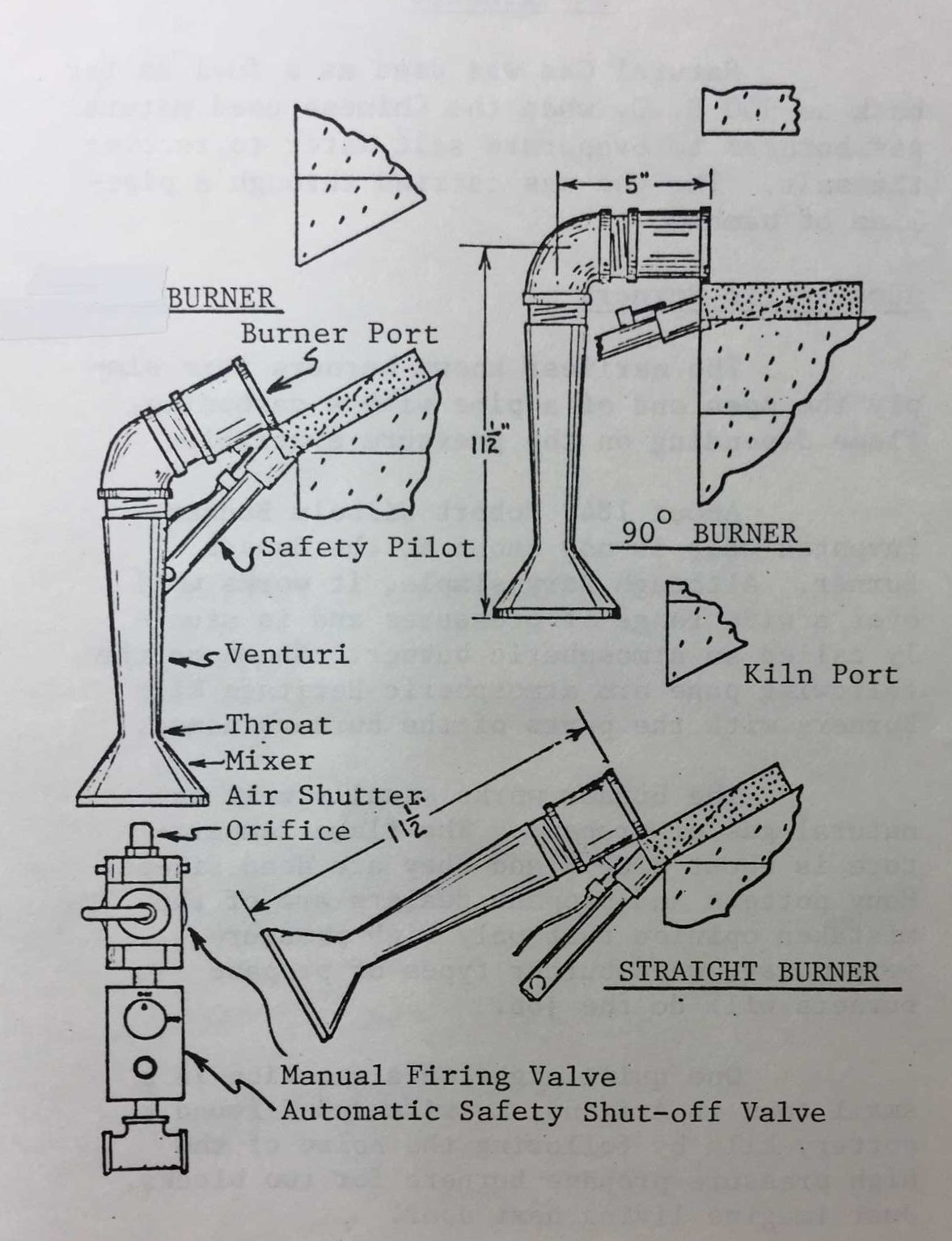
On any mono port or single port burners there are a few precautions one must observe.
Propane needs 4 times as much primary as does natural gas. Primary air is the air which is mixed with the gas because of the venturi action in the air-mixer, throat and venturi caused by the velocity of the jet of gas from the orifice. Primary air makes up about 1/3 of the air required for combustion.
The air which enters the burner port around the burner and around the outside of the secondary air will determine whether the atmosphere in the kiln will have complete combustion and be oxidizing because of the excess oxygen which is not required or have incomplete combustion called a reducing atmosphere, is smothering and producing excessive carbon monoxide.
Two factors control the amount secondary air that will enter the kiln port:
The port area: A port area of about 1 in2 for each 8000 BTU of gas input has proven Being too small may make it hard to get complete combustion and air oxidizing firing. Too large will have little effect since closing the flue damper will reduce the air passing in the port.
The Flue Damper Setting: The most influential factor on the amount of air entering the kiln
port is the damper setting. If the burner flue products cannot exit from the kiln, then secondary air cannot get in through the burner port. As mentioned in the chapter on combustion; the position on the neutral pressure point in relation to the port is raised or lowered by the damper setting. This statement is also true of some other factors if not correctly proportioned. These are the openings through the setting floor which if too small have the same effect as a closed damper, and insufficient chimney height which also has the same effect. Stacking the wares so tight and close as to overly restrict the passage of flue gases through the kiln also would have the effect of too restricted a damper setting.Operation
Atmospheric gas burners are extremely easy to adjust and operate and should certainly be the first choice in the vast majority of kilns. Though some would argue the point; my own choice is to use a number of smaller burners rather than two large burners. More, smaller burners have the ability to more evenly distribute the heat throughout the kiln and to make it possible to adjust individual burner inputs to attain this end.
A small disadvantage to all monoport (single port) atmospheric burners is the turn down ratio. For approval or certification a burner must not flash back and burn in the mixer at over ½ of its rated input. Most will actually flash back at about ¼ to ⅓ of the rating so one must take care in the turn down. Flash back can be detected by a rushing or whistling sound in the burner mixer or venturi and give a carboning fire. For lower turn down with propane it is usually necessary to partially close the air shutters but this is usually not necessary on natural gas.
Power Burners
Although there is definitely a place for power burners in the pottery field it has been our experience that we have usually only had to apply power burners to kilns to make up for some fault or inadequacy in the kiln design. The usual reason is the lack of combustion space for complete combustion atmospherically.
However, in the firing of Raku kilns, the picture is entirely different. Here, the power burner provides the quick recovery required each time the kiln is opened.
Generally speaking, we have found that with natural gas it is best to use a power burner, whereas, with propane, and the much higher pressure available, power burners are unnecessary.
A power burner is much easier to construct than most people would expect and are also more expensive to buy commercially than most potters would wish to spend. Shown on the following page is a simple home-built power burner of about 300,000 BTU. The discharge of a cannister or tank type vacuum cleaner, although noisy, can often be used for the blower of a burner up to about 500,000 BTU.
In the construction and use of power burners there are several gas regulations which must be observed.
Air Failure : A low air pressure switch must be provided as shown to cut off gas in the event of a power or air failure and such that gas cannot come back on unless the burner is started up again manually.
Air pressure differential switch - This is the most simple to apply and only requires ¼" tubing in the air inlet and directly downstream of the blower discharge.
Sail switch - Some blowers have a sail switch built into the blower air discharge as part of the blower.
Centrifugal switch - In most areas a centrifugal switch is acceptable provided the blower shell is keyed to the shaft or held with more than one lock screw.
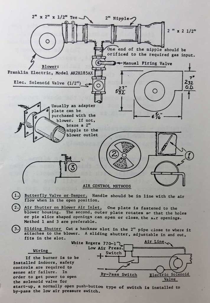
The above air switch is wired to An electric solenoid valve in the gas line with a manual momentary switch so that the burner cannot start up unless manually started. This is necessary because without it, restoration of power after a power failure would otherwise open the gas valve when there may be no source of ignition.
Although advisable, the above requirement may not be enforced in some areas if the kiln is outdoors.
Operation - The operation of a power burner is a little more involved because of the need for air and gas adjustment simultaneously.
Some people may be a little afraid of a power burner at first but this will ease as they become more familiar with its adjustment. Since most kilns with power burners will have at the most 2 burners, adjusting the burner to get a low enough fire for a slow rate of temperature climb will take careful air and gas adjustment.
The building of a gas kiln entails a considerable outlay of both time and money, so it is wise to give considerable thought to the planning and location of the kiln. Whether the location is permanent, or on a temporary basis, a good location is essential, not only to the performance and safety, but also to assure a reasonable durability.
Some of the points to be considered:
To start off on the right foot, the first step should be to speak to the local gas or building inspectors; called in the regulation "The Authority Having Jurisdiction". In some areas, this may also come under the Fire Marshall.
It is surprising to many people to find out that inspectors are usually nice people and very willing to help when given proper co-operation. Remember though, that many inspectors have never seen a kiln and that in most areas, have no written regulations to guide them.
ZONING
Be sure to check the zoning regulations in the area you plan to build the kiln. If the kiln is a hobby, you should have no difficulty in any residential area. However, should you wish to sell or display wares, you will probably have to find an area zoned for light commercial. In some cases, permission may be easier to obtain if a school is operated in conjunction with the business.
You have probably decided already if you will building indoors or outdoors, so let's look at the features and problems of each.
Outdoor Kilns
The kiln would be it is totally exposed, or also, if it is covered by a shed or roof, which is designed solely to protect the kiln from the elements.
Proximity and Height of Buildings Close-by
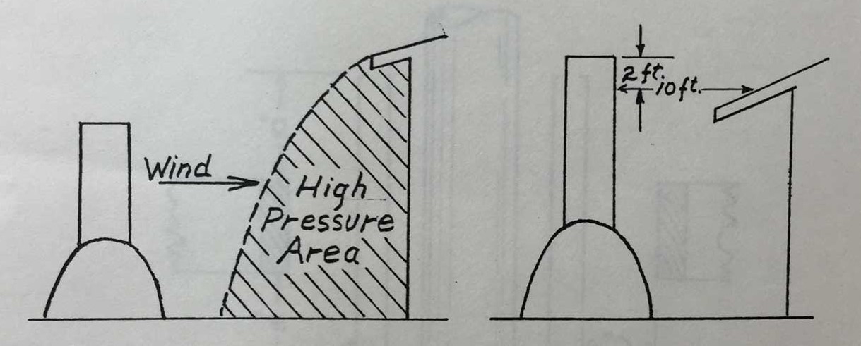
We know of a kiln built close to a house having a high peak roof, and as a result, the kiln chimney is 23 feet high and probably cost more than the kiln. The C.S.A: B149.1 Code calls for a vent terminal to be 2 feet above any structure within 10 feet as follows.
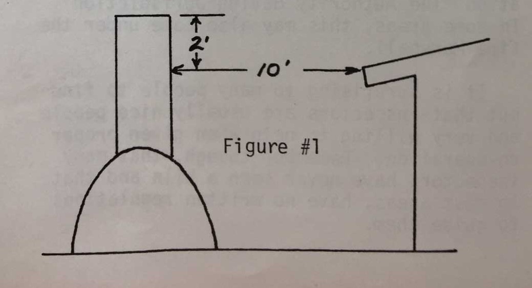
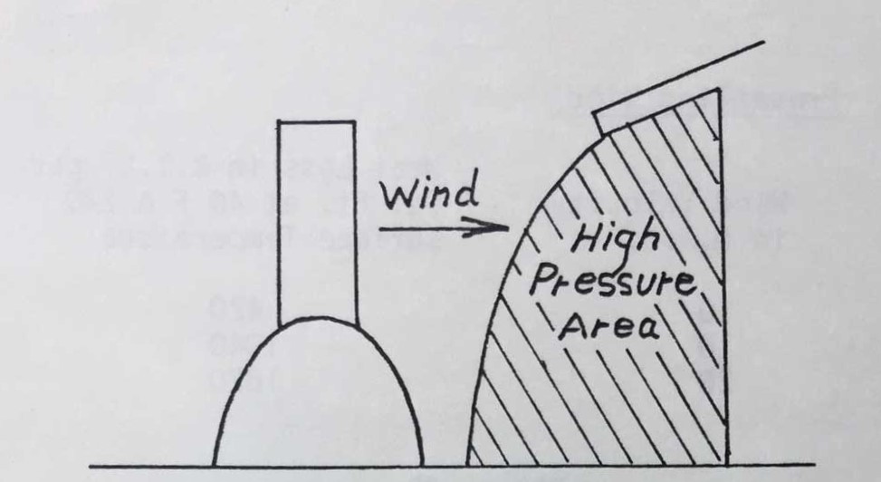
The drawing below illustrates the high pressure area on the windward side of a building. To be doubly sure to stay out of this high pressure area, build at least as far from the building as the building is high. The same stands true for the lee side, except that a negative or low pressure area is created. Extend the chimney to terminate 2 feet above any part of the building within 10 feet
If the kiln is in a shelter attached to the house or garage, the common wall should have at least a one hour fire rating.
Elevation and Drainage
The outdoor kiln site should be well drained and not in an area where water will gather. If you must locate the kiln in an area of poor drainage, have 2 or 3 feet of gravel beneath the foundation and then build up the kiln floor higher by the use of concrete blocks or common brick. Be sure to have the top of the concrete foundation a few inches above ground level.
Prevailing Wind
Note below the great effect that wind has on the heat loss from a kiln at 40°F outdoor temperature, and with a kiln wall outside temperature of 220°F.
| Wind Velocity in MPH | Heat loss BTU/ft3 at 40°F & 220°F |
| 0 | 420 |
| 10 | 1040 |
| 20 | 1620 |
Note that the heat loss at 20 MPH winds is almost four times as high as with no wind. It is therefore good economy to protect the kiln from winds and to insulate the outdoor kiln very well. A metal garden shed is not too expensive and is excellent protection, but be sure there is enough access space at the sides.
Proximity of the Chimney Outlet to Windows
In a reduction firing, excessive quantities of carbon monoxide are produced. It is therefore extremely important that a kiln chimney does not terminate anywhere close to a window which can be opened, or a building air inlet.
The Gas Source
There are 2 common types of natural gas distribution systems. In the older low pressure system, the gas pressure in the mains is con trolled to about 4 ounces (7 in-water-column) by a district regulator station. With this the line into the house is usually sized only to handle the load for the house. The addition
on the kiln would probably mean having to enlarge the service from the main and entail considerable expense.In the newer medium pressure system, the service is at 10 to 15 psi, and regulated down to 4 ouches, just before the meter. In this case, the service will usually handle the addition of a kiln, but care must be taken that the line from the meter to the kiln is properly sized. Consult your Gas Company for information regarding size of service and metering.
Indoor Kilns
Because of the concentration of carbon monoxide generated during a reduction firing, a gas kiln should never, and would probably not be permitted, within the living area of a residence.
If it is located in a studio or shed attached to the house, the common wall should have one hour fire rating. Check with the local fire prevention or building inspection department for information.
Separating the Kiln Area from the Work Area
Special precautions should be taken where a kiln is to be located in the same studio or building as the work area. We have taken CO tests in two studios where the potters suffered headaches cause by CO leakage during a reduction firing. An air tight separation (acceptable to the enforcing authority) should be provided to separate the kiln area from the work area.
Ventilating the kiln area
The aforementioned kiln area should have a fresh air inlet located near the floor level
and a ventilation air outlet located at ceiling level as close above the kiln as possible. Remember that if an exhaust fan* is installed, sufficient air inlet must be provided so that a negative pressure is not established within the building which could reverse the draft in the kiln and appliance vents and create a hazardous condition.Access and Clearance
Access for Lighting and Adjustment
If the burners are located on both sides, it is important to plan sufficient space to light and service the burners. For this, three feet is ideal with two feet as a minimum. If the space on each side is limited, but there is sufficient on the front and rear, it would be best to place the burners at the front and rear and fire parallel to the bag wall. Remember that the outside dimensions of most down-draft kilns will be approximately 36" wider than the usable space between the bag walls.
Clearances
We cannot stress too strongly the importance of our cooperation with local inspection authorities.
Because of differing regulation in different areas we can give here only general recommendations which we suggest you show to your local authorities and get their approval.
The minimum clearance from the top and sides of the kiln to combustible material should be not less than 48". This could be reduced when the combustible material is protected by a method acceptable to the inspection authorities but in no case should the clearance be
less than 24".When an up-draft kiln is vented by means of a canopy and single wall metal vent, the clearance from the vent to combustible construction should not be less than 18". This clearance could also be reduced when the combustible material is protected by a method acceptable to the enforcing authority.
An interior metal chimney from a gas fired kiln should have a minimum clearance of 3 ft. from combustible construction except that where a metal chimney passes through combustible roof construction the clearance may be reduced to 12" provided the chimney is guarded by a metal thimble extending at least 9" above and below the roof construction. The thimble must have double walls with a ventilated space between the walls. The clearance between the metal thimble and combustible construction must not be less than 6".
Again we would mention, be sure to check regulations in your particular area. The regulations and inspection authorities are there for our own good.
Now as in the past, most kilns are built by the potters who fire them and though they have been in use for thousands of years, basically the changes have not been too significant. The same is not true however in construction materials and there is now a wide choice available in addition to the traditional firebrick used for centuries.
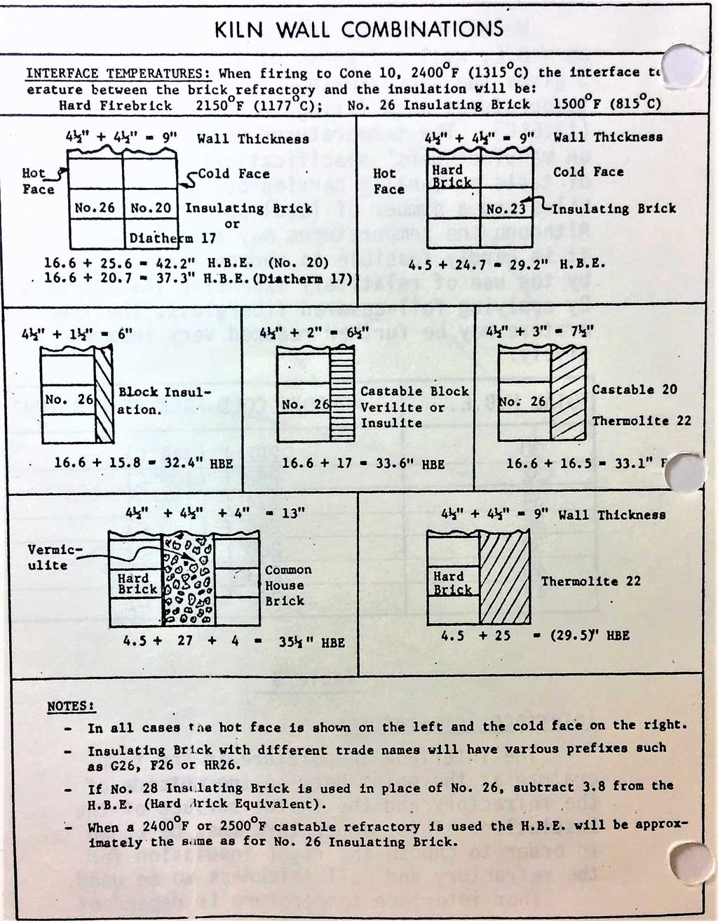
In refractory materials there is hard firebrick, lightweight insulating firebrick, numerous cast able refractories and fibrous ceramic in several forms. Insulating materials include insulating firebrick, several castables, block insulations, loose fill and fibrous ceramic.
We hope this information will help in choosing a successful combination of materials and as an approximate guide to the interface and cold face temperature.
This paper has been compiled from the specifications of several manufacturers; from the information gained by the construction of three test kilns
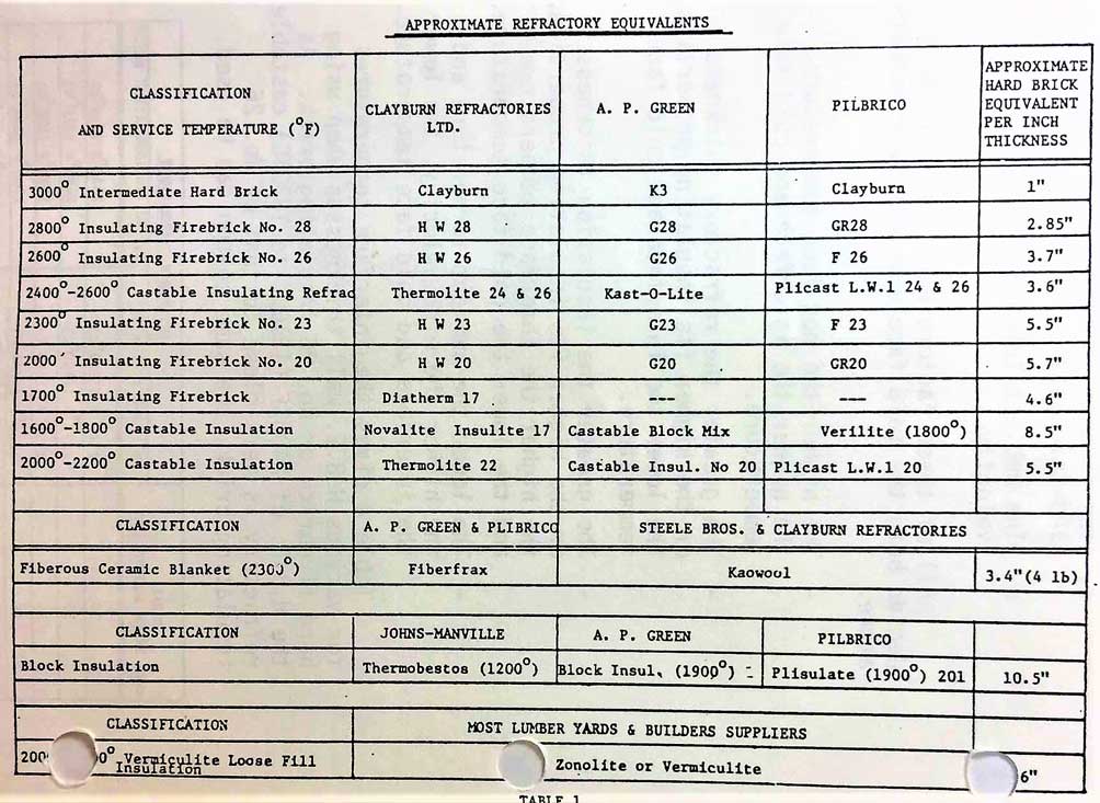
of different materials and from tests carried out on several successful local kilns.First, let's consider the method used for comparing refractory or insulating materials. The accepted measure of thermal insulating ability is thermal conductivity. Thermal conductivity is the measure of heat flow in BTU (British Thermal Units) through a material per square foot, per degree Fahrenheit, per inch of thickness. It can be seen therefore that the thermal conductivity (k) factor varies as the temperature on the sides increase. Most manufacturers specifications show the (k) factor by a line graph at various temperatures up to the maximum recommended temperature for the product. For example the (k) factor of hard firebrick is 10.2 at 2000°F and 11.1 at 2400°F. From the (k) factors it can be determined that the insulating property of 1" of No. 26 insulating brick is equivalent to 3.7" of hard firebrick. By comparing the (k) factor of the various materials to that of hard brick, the hard brick equivalent (H.B.E.) is obtained and is a convenient means of comparing insulating properties. The (k) factor and thus the H.B.E. vary according to the mean or average temperature of the material. It would therefore be impractical in a paper of this size and simplicity also, products of similar properties by different manufacturers have been grouped together and their H.B.E. averaged. All temperatures shown can only be an approximation; however, we believe the resulting error will be of little significance.
Now let's look at a brief summary of the Refractories and Insulations to be discussed.
Hard Brick:
Intermediate duty fire brick such as Clay burn, Defco, Bison etc. are satisfactory for operating temperatures up to 3000° F (1649°C). Their cost is approximately 60% that of insulating brick, are extremely long lived, but unfortunately low in insulating properties. This means they must be combined with insulation with a service temperature of around 2150°F (1177°C). Since they are hard, it is best to avoid special shapes which must be ordered or else cut on a special brick saw. It is worth mentioning that we have seen several kilns using hard brick as insulation and No. 26 Insulating brick as the refractory. Such "inside out" kilns work satisfactorily, however, hard brick has very little insulating properties but would greatly outlast the insulating brick if used as the refractory.
Insulating Brick:
Insulating fire bricks weigh about ¼ to ⅓ that of hard brick and have about 3 to 5 times the insulating properties. Their cost is close to double that of hard firebrick and their life is much shorter. Since they can be cut to shape with an ordinary hand saw, they are very easy to work with and are probably the best choice for most "amateur brick layers!'. They are designated by number indicating the service temperature 20, 23, 26 and 28 for temperatures of 2000°, 2300°, 2600° and 2800°. The number is prefixed by letters depending on the manufacturer such as G, K, HW and GR. No. 26 is the one most commonly used for the hot face refractory with Nos.
20 and 23 used for insulation of soft or hard brick.Castable Refractories:
Castables in the range above 2400°F (1315°C) can be used as a monolithic refractory while those under 2200°F (1204°C) are excellent for insulations. Castable refractories certainly have their place in kiln construction but it must be remembered that a monolithic component is liable to crack and this must be provided for. One way is to construct the walls of several sections with Fiberfrax or Kaowool between the joints. The insulating properties of semi insulating castables are approximately equal to that of No. 26 insulating brick but cost is about 15% higher. To ensure the proper strength, care should be taken to ensure that exactly the recommended amount of water is used in the mix.
Fibrous Ceramic Blanket:
For test purposes we built a kiln of 4 lb. density Fiberfrax and Kaowool blanket cemented inside a metal box. With the kiln at 2400°F and 2" of ceramic blanket, the outer or cold face temperature was about 555° F. This approximates the manufacturer's specifications and confirms that its H.B.E. is about the same as No. 26 insulating firebrick. Its cost makes it very expensive if used only as an insulant and many other insulants with much higher H.B.E. are much cheaper. It's properties make it excellent for use as a sealing material for expansion cracks and joints, and for a temporary or low temperature portable kiln such as a Raku kiln.
Using ceramic blanket, a very convenient kiln door can be made which is so light it can be hung on ordinary hinges.
Both manufacturers have a wide range of products such as blankets, boards, loose fill and tamping mix.
Insulating Brick:
As mentioned under refractories, insulating brick such as No. 20 and 23 are easy to use but quite expensive. Because the lower the number, (and service temperature), the lower the cost and the higher the insulating properties, it is unwise to use a brick of higher number (and temperature) than is needed. Comparing both cost and thermal conductivity No. 20 is about 60% of the cost of No. 26 and 85% of the cost of No. 23 insulating brick.
Usually No. 23 should be used to insulate hard firebrick and No. 20 used to insulate No. 26 (the latter would be about the most expensive of all combinations).
Castable Insulations
Castables with a service temperature of over 2150° F (1177°C) such as Duralite 22, Castable Insulation No. 22 or Plicast LW124 can be used with hard firebrick. Cost may be slightly less than that of No. 23 insulated brick for equal H.B.E.
For use with insulating firebrick, castables such as Verilite, Novalite, and Castable block mix all in the 1600°F (871°C) range are suitable insulants of very high efficiency. Castable
insulants in this range cost about 1/4 the cost of using insulating brick of equal H.B.E.Block Insulations:
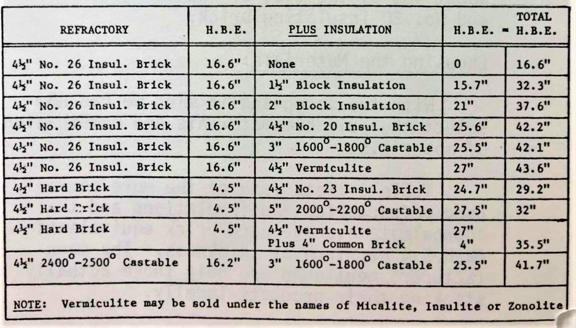
All the refractory suppliers have a block insulation rated for 1900°F (1038°C). They have a H.B.E. of 10.5 to 14 and come in sizes of 6" x 18" or 12" x 36". To save work, use the size of 12" x 36". The combination of No. 26 insulating brick refractory and 1½" or 2" of block insulation is the easiest to build kiln at a medium cost. Considering the H.B.E. of block insulation, its actual cost is just over 1/3 that of insulating with No. 20 insulating brick.
Thermobestos is a block type of insulation rated for 1200°F (649°C) so a higher temperature insulation would be needed between it and the refractory to get the interface temperature down to below 1200°F (649°C).
Loose Fill Insulation:
There are two common types of loose fill insulation, Vermiculite and Ceramic' bulk fibre.
Ceramic bulk fibre such as Koawool or Fibrefrax comes in densities of 6, 8 and 10 lb. and for use up to 2300°F. At 1000°F (538°C) mean temperature the 6 lb. density has an H.B.E. of approximately 9" per inch of thickness. Because of its cost it is unlikely to be chosen for insulation.
Vermiculite, Micalite or Zonolite have a fusion temperature in excess of 2500°F (1371°C) and are the least expensive of all insulants. For test purposes, we
built a kiln using 4½" of No. 26 insulating brick with 3" of Zonolite as insulation retained in place by a light metal casing. Its good performance and low casing temperature indicate a H.B.E. of approximately 32". This kiln has been used for five years by a local potter. We know of several other successful kilns where it is used as insulation for both hard and insulating brick. Possibly the least costly to build kiln of all with total H.B.E. of 35" is by using hard brick, 4½" brick. The resultant wall is 13½" thick and so takes up more space than most other constructions. Access should be provided at the top of the kiln to add more fill should some settling take place. To prevent particles of the fill working their way between the firebricks, it is wise to place a couple of layers of asbestos paper on the outside of the firebrick. A kiln built in this way costs about 40% of the cost of one using No. 26 and No. 20 insulating brick.Choosing the Materials:
With the foregoing in mind we can now select the suitable materials and combinations
Table 1 lists some of the more commonly used refractories and insulations and their approximate average hard brick equivalents (H.B.E.) per inch of thickness. The manufacturers mentioned are only those actually stocking their products, locally.
Table 2 lists some of the practical combinations of the refractories and insulations from Table 1, and their approximate total H.B.E.
Please note that the H.B.E. shown has been arrived tit by averaging the "k" factor from three manufacturers' specifications and therefore may not agree with the specifications shown by any one manufacturer. The type of refractory must be decided upon according to its temperature use, type of glazing, length of life desired, and cost. It is wise in this regard to ask the advice of instructors, experienced potters and suppliers. This is especially true in cases such as salt glazing, where a high duty type of hard brick must be used in order to obtain reasonable kiln life. Once the refractory and total wall thickness has been decided upon, we are ready to design the wall and roof, or to check the interface and cold face temperature within the limits of the materials mentioned in this paper.
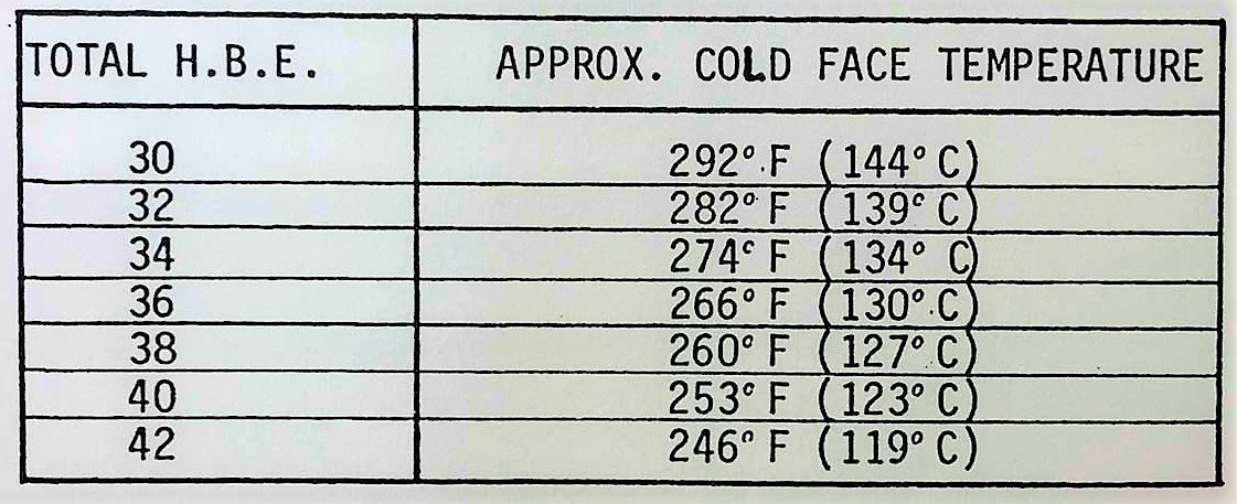
Cold Face Temperatures
We believe that a good kiln should have an H.B.E. wall thickness of 32" or more. Table temperatures when firing to cone 9 or 2400° F (1316°C). The temperatures shown are based of tests personally carried out on two test kilns and a number of local potter's kilns. Although the temperatures may appear high, it is hardly feasible to reduce them further by the use of relatively expensive insulations. By applying foil-covered fiberglass, the temperature may be further reduced very inexpensively.
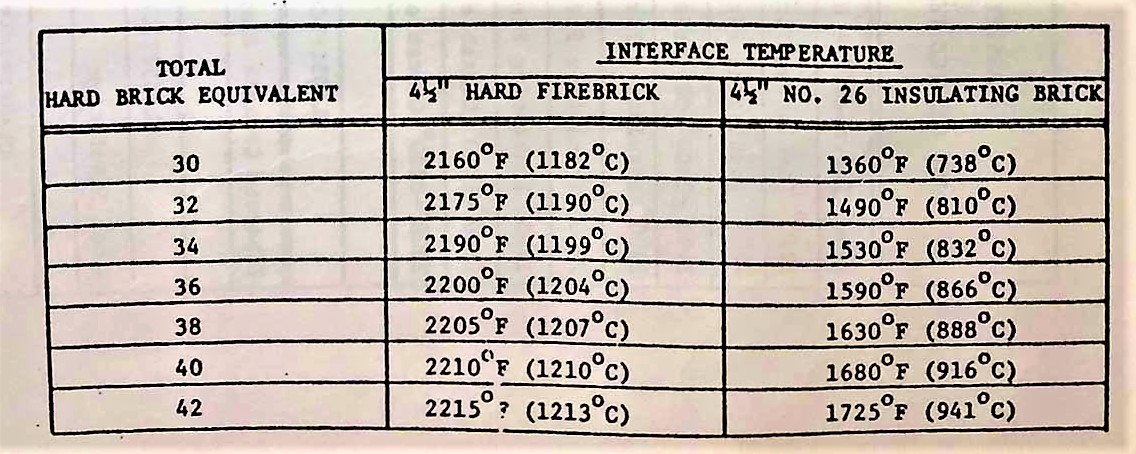
Interface Temperatures
The interface temperature is the temperature at the point between the outside of insulation. This temperature must be known in order to choose the right insulation for the refractory and wall thickness to be used.
There interface temperature is dependent upon several factors such as:
All of these factors work together to decide both the cold face and interface temperature.
The higher the hot face temperature, the higher the interface and cold face temperature.
The greater the refractory thickness or the higher its insulating properties, the lower the interface and cold face temperature.
The greater the insulation thickness or the higher its insulating properties, the higher interface temperature, and the lower the cold face temperature.
The lower the ambient temperature and the higher the wind velocity, the lower the interface and cold face temperature.
Table below gives the interface temperatures for various H.B.E. wall thicknesses when using hard firebrick or No. 26 insulating brick. As the H.B.E. of 2400°F (1316°C to 1370°C) castable refractory is very close to that of No. 26 insulating brick, the same column can be used.
The data summarized here consists of excerpts from C. S. A. Standard B149.2, "Installation Code for Propane Burning Appliances and Equipment", or from the Province of Alberta, Department of Labor, Gas Protection Branch, Quarterly Bulletin. These are two rather formidable Codes to try to reduce to a few simple pages, but we hope this attempt will be of some use. We must strongly recommend that for a more complete report these two publications should be obtained or your problems and plans fully discussed with the authority having jurisdiction in your area.
PHYSICAL PROPERTIES OF PROPANE:
It is a hydro carbon (made up of hydrogen and carbon) with the formula C3H8.
Considered non-toxic.
Almost odorless before addition of odorant for safety.
BTU per ft3 of gas: 2,520.
BTU per Imperial gallon of liquid: 110,000.
Weight per Imperial gallon of liquid: 5.1 lbs.
Specific Gravity of gas: 1.5 (Air 1:0).
Specific Gravity of liquid: 0.51 (Water 1.0).
Lower and Upper limits of flammability: 2.15% to 9.5%.
Boiling point: -44°F.
Ft3 of air to burn 1 ft3 of gas: 24.
Ft3 of gas per Imperial gallon of liquid: 43.6.
Since propane boils at 44°F, vapor (gas) cannot be withdrawn from tankage below this temperature. Even at temperatures much below -30° F, the chilling by evaporation lowers the tank temperature below usable levels.
The amount of vapor which can be withdrawn from a tank or cylinder depends upon:
The heat level of the atmosphere above the boiling point of propane (-44° F).
The area of the container surface in contact with the liquid propane through which the atmosphere can transmit heat to the liquid propane.
At lower temperatures, the amount of vapor available is less than at higher temperatures. There is also less vapor available if the tank is only partially filled. It is therefore important to use a storage tank large enough to meet the demand of the maximum kiln firing rate plus any additional heating load at the lowest air temperature at which the kiln is liable to be fired.
Table No. 1 gives the approximate vaporization in BTU per hour for commercial propane from containers of various glazes at varying temperatures when 20% of the propane capacity of the container remains in it.
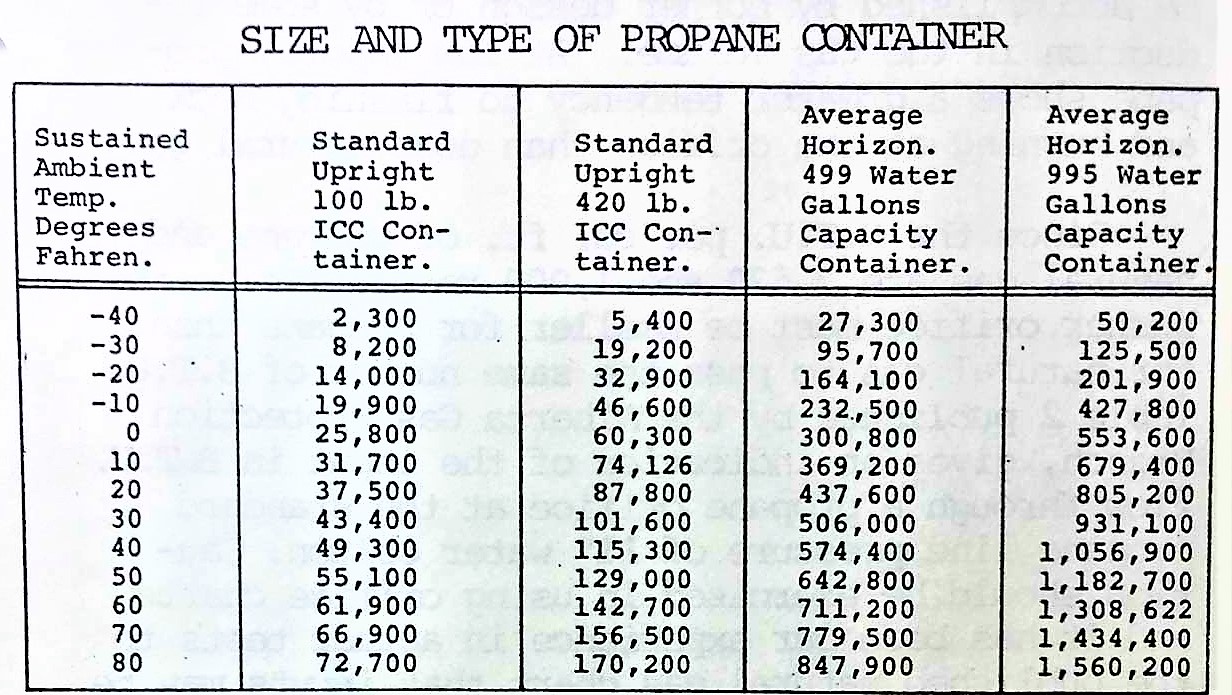
In installations which require a large BTU withdrawal, the addition of a vaporizer will decrease the amount of tank storage capacity required to supply adequate withdrawal rates at low temperature and, in some cases, may be the only practical solution to obtaining the required vaporization.
Heat applied to a storage tank by any unapproved means to increase the vaporization, is a dangerous practice and should not be carried on under any circumstance.
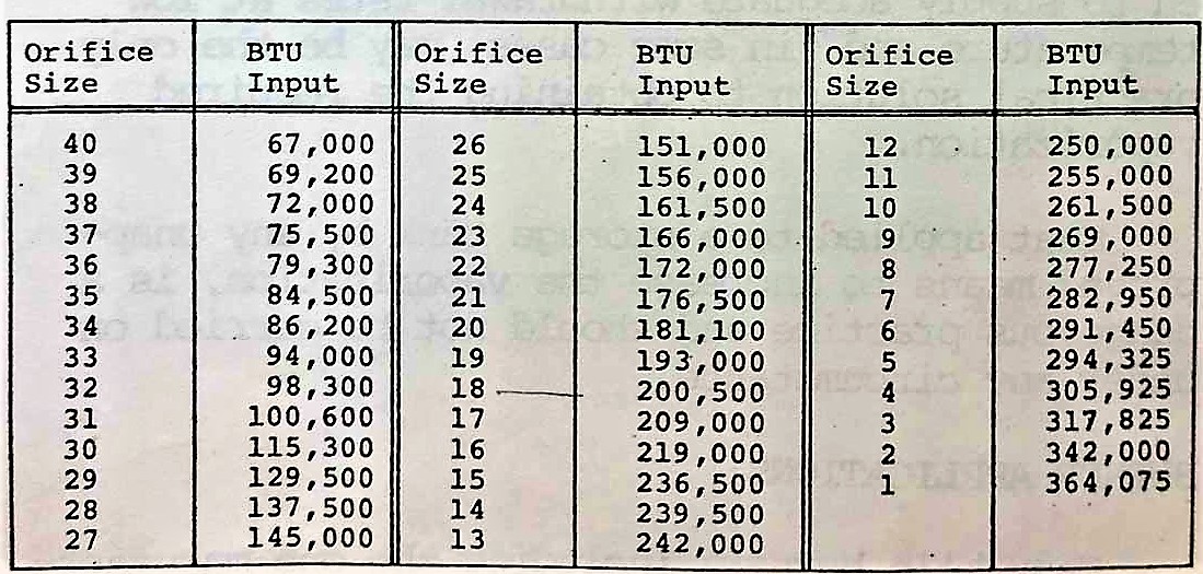
Many kiln burners including the one manufactured by the writer, will operate oN propane or natural gas but with different flame characteristics. As will be noted under properties, propane requires 24 ft3 of air for each ft3 of propane, as compared to 1O ft3 of air per ft3 of natural gas. This increase in air required can
be accomplished by burner design or by some reduction in the gas volume. At low inputs, propane shows a greater tendency to flashing back and burning at the orifice than does natural gas.Since the BTU per ft3 of propane and natural gas are 2,520 and 1,000 respectively, the burner orifice must be smaller for propane than for natural gas to pass the same number of BTU Table 2 published by the Alberta Gas Protection Branch, gives an indication of the input in BTU flow through a propane orifice at the standard propane line pressure of 11 in-water-column. Caution should be exercised in using orifice charts and it has been our experience in actual tests to the published natural gas chart that inputs may be slightly higher than those shown. Sizes shown are D.M.S. Wire gauge.
Just as the smaller orifice is used because of the higher BTU content of propane, smaller sized pipe lines are normally used. Propane piping installations must comply with the C.S.A. B149.2 - 1969 Installation Code and with the requirements of the Alberta Gas Protection Branch. Following shows the size of lines required from tank to burners using schedule 40 piping and with the pressure regulator on the tank set for 11 in-water-column pressure.
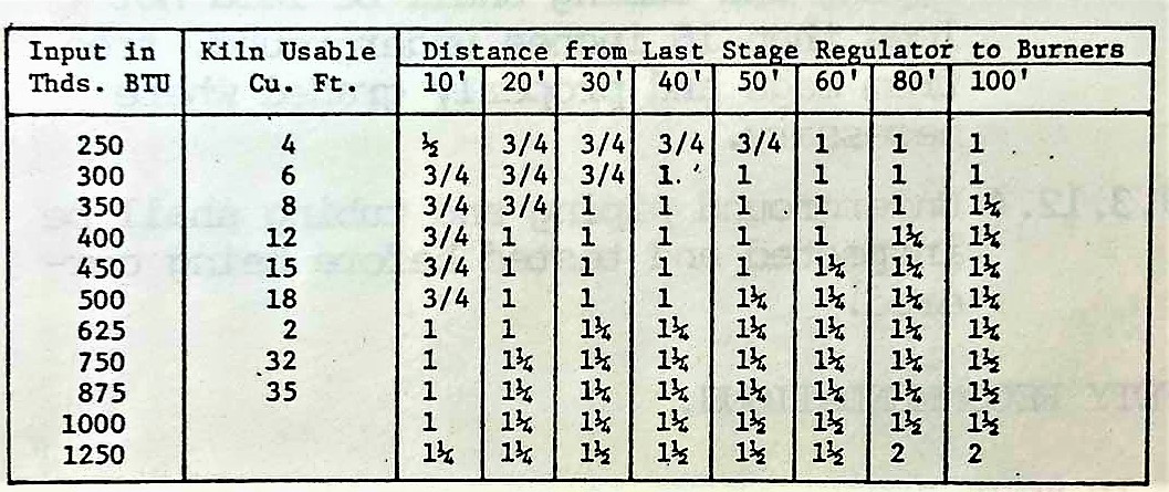
All installations should be done by a licensed gas fitter who should be familiar with the applicable gas codes.
Below are just a few clauses from b149.2 - 1969 which may apply to kiln installations.
3.9.3.3.3 : Piping and tubing shall not be run inside walls or partitions, unless protected against physical damage. This does not apply to piping and tubing which is run through walls or partitions.
3.9.3.7.1 : Piping or tubing shall not be run in inaccessible or concealed spaces where it cannot be Inspected and tested for leaks in its final position prior to be concealed, or when undetected leakage might cause dangerous accumulation of gas. This requirement does not apply to piping or tubing which passes directly through walls or partitions.
3.9.3.12.1 : Underground piping shall not be installed with threaded fittings.
3.9.3.12.3 : Piping and tubing shall be laid not less than 15 inches underground, free from sags and properly graded where necessary.
3.9.3.12.4 : Underground piping and tubing shall be inspected and tested before being covered.
In most areas, there is no installation code written exclusively for gas kilns. Be sure check with the authority having jurisdiction your area for applicable regulations and also for advice.
We would strongly recommend that the following be used as a guide for the safe installation and operation of the kiln.
INSTALLATION OF KILNS :
A gas kiln should not be installed within the living area of a residence.
When a gas kiln is installed in a building
or a room attached to an occupied building , the common wall or walls should have a 1 hour fire resistance rating.Where a gas kiln is installed in a room adjacent to a work area, means should be provided to screen or partition the kiln area from the work area by means acceptable to the enforcing authority.
SAFETY CONTROLS:
Safety shut-off controls should be provided on indoor kilns for all burners which are not under constant supervision. This requirement shall not apply to kilns installed outdoors or in an unoccupied building used solely to protect the kiln from the elements.
Kilns having on-off automatic temperature controlled burners must be provided with safety shut-off controls on all burners.
Kilns fired with L. P. propane gases must have safety controls which cut off both main and pilot burners when required as in (a) and (b) above.
NOTE: In Alberta, automatic safety shut-off is required on all propane fired kilns regardless of location .
COMBUSTION AIR & VENTILATION:
The kiln room or kiln area (as in l (b) or (c) should be provided with a combustion air inlet close to floor level, and a ventilation outlet at ceiling level sized to be 50% greater than that required by Clause 4. 2.1. of C. S. A. B149.2 - 1969.
CLEARENCES AND VENTING OF INDOOR KIINS
The minimum clearance from the top and sides of the kiln to combustible material shall be 36". This clearance may be reduced when protection is provided in accordance with Table 29 of C. S. A. B149.2 - 1969.
The clearance between a brick chimney and combustible material should not be less than 18". This clearance may be reduced when protection is provided in accordance with Table 29 of C. S.A. B1492 - 1969.
The information in this paper is primarily based on the results of a study of successful kilns carried out over the past several years.
While some potters may believe there is a mystique, understood only by a few; people experienced in the design of industrial gas equipment would consider a kiln just another gas burning device. By comparison with today's sophisticated industrial equipment used by many processors, foundries and metal fabricators it is the utmost in basic simplicity.
However in its simplicity it is still necessary to plan the kiln properly to be able to fulfil the potters wishes for top quality firings with the desired atmosphere, in safety and with as reasonable as possible economy.
We do not wish to indicate that the methods and proportions mentioned are the only ones which will provide satisfactory results. The survey of kilns, illustrated that a wide range of proportions could still give satisfactory results. However, in some cases, the satisfactory results were only obtained after the potter had learned to compensate for inadequacies in the kiln itself. We hope that the information shared may help kiln builders avoid some of the pitfalls observed, and be of some assistance in encouraging better and safer kilns.
Where do we Start?
This always seems to be the first question. One of the most important decisions is what type and size of wares will I be firing in 1, 2 or 5 years from now?
Would I rather fire a small kiln more often or a larger kiln less often? We have heard several kiln but have never heard one wish for a smaller kiln. Remember too, - the larger the kiln, the less the initial cost per usable ft3 and also the larger the kiln, the less gas it used per usable ft3. An 8 ft3 kiln will require about 35,000 BTU of gas per usable ft3 while and 80 usable ft3 kill will only need about 14,000 BTU per usable ft3.
Be sure to ask the opinion of experienced potters or qualified instructors who have built their own kiln before making hasty decisions.
DEFINITONS
Total Kiln Volume in this paper, refers to the volume within the kiln as follows:
Width: The maximum internal width, hot face to hot face.
Height: From the top of the flue exit to the top of the inside of the arch.
Depth: From the inside of the door to the inside of the rear wall.
Usable Kiln Volume refers to the space for setting wares as follows:
Width: The distance between the bagwalls
Height:
With a slotted brick floor, the height would be from the top of the kiln arch.
Where a kiln shelf is used as the floor, the height would be measured from the kiln shelf to the inside top of the kiln arch.
Depth: From the inside of the door to the inside of the rear wall.
Determining the Volume
Catenary Arch
Area = 4/3 x a x b
Volume = 4/3 x a x b x depth
Sprung Arch
Since the formula for determining the volume within the sprung arch is quite complicated, the writer recommends the following simplified estimate. For the height, take the height to the edge of the arch (a). To this, add 2/3 of the rise (b). Check this out on graph paper, and you will find it quite close.
First Things First
The first decision is the floor space and then the height you need above the floor.
The most commonly used sizes of kiln shelves are: 10" x 22", 12" x 24", and 14" x 28".
In the kiln, we will need about 1" to 1 ½" between and all around the shelves. Since a standard firebrick is 4½" x 9" x 2½"
thick, it is best to keep all dimensions in width and depth to functions of 4 ½" or 9" and in height to functions of 2 ½".Planning the Proportions
As an example, let's plan a medium sized kiln of approximately 25 usable ft3 using hard or insulating firebrick, having a sprung arch and using three 12" x 24" kiln shelves. It is generally accepted that the inside total of the kiln should be roughly a cube in proportion.
The Setting Floor
In following image you will see how the three 12" x 24" shelves fit in a floor 27" x 40 ½" which is 3 bricks by 4 ½ bricks. The space between and around the shelves is just adequate for good flue travel. Openings through the setting floor will be mentioned later.
Figure 3
The Width
Since the kiln shelf is 24" long and space is needed around the shelves, a width between the
bagwalls of 27" (3 bricks) works out well.From there we can work outwards to determine the outside width of the kiln and foundation.
| Inches | Bricks | |
| Space between the bagwall | 27 | 3 |
| 2 bagwalls @ 2 ½" | 5 | |
| *Combustion space between the bagwall & kiln wall 2 @ 6 ½" |
13 | |
| Total inside width | 45 | 5 |
| Plus hot face refractory 2 @ 4 ½" |
9 | 1 |
| 54 | 6 | |
| Plus insulating brick 2 @ 4 ½" |
9 | 1 |
| Total outside width | 63 | 7 |
* It will be noted that the only variable space is the space between the outer wall and the bagwall. His can be varied slightly to make the kiln width work out to a function of 9" or 4 ½". The 6 ½" is fine for this size of kiln but would be increased for larger kilns
The above assumes that in a kiln of this size most would prefer a 9" thick wall since at 4 ½" wall is not recommended with a wall of this height. If other insulations are used in place of 4 ½" of insulating brick, add double the thickness of insulation to the 54" width.
| Inches | Courses | |
| Above the foundation for insulation | 5 | 2 |
| Height of flue exit | 10 | 4 |
| Kiln floor thickness | 2 ½ | 1 |
| Total | 17 ½" | 7 |
Note: If kiln shelves are used for the floor it will be ¾" thick.
Since the kiln is 45" wide inside and we want the result close to a cube, we will want about 45" from the floor to the top of the arch. With the arch mentioned the rise is approximately 9". The distance then from the kiln floor to the bottom of the arch will be 45 - 9 + 36". Since 36" is not a function of 2 ½, the height can be 35" so there are 14 courses of bricks from the top of the kiln
floor to the top of the kiln wall at the outer edge of the arch.| Summary of Height | Inches | Courses |
| Insulating course on Foundation | 5 | 2 |
| Height of flue exit | 10 | 4 |
| Floor thickness | 2 ½ | 1 |
| From floor to top of side wall | 35 | 14 |
| 62 ½" | 21 |
The Depth
In keeping with having the total inside close to a cube, the depth from the inside of the door should be approximately 45". This however, does not work out well for kiln shelves. Since we want 1 to ½" space between shelves, 40 ½ (4½ bricks) works out better see Figure 3. With these inside depths and the long reach in; thought should be given to constructing a car kiln. However, the extra steel work involved would prove costly to those unable to do their own welding. With the inside depth of 40½" and assuming that the door will be bricked in 2 thicknesses, the outside depth will be 40½ + 4½ (rear wall) + 9" door + the rear wall insulation. If 4"; of insulating brick is used for insulation, the total outside depth of the kiln will be 58½" or 6½ bricks.
The Setting Floor and Its Openings
The correct sizing and position of the floor openings has much to do with having an even firing from front to rear and side to side. A large number of smaller slots are preferable to the openings around kiln shelves used for that purpose.
Our floor, 3 bricks wide, permits the use of
fire brick if desired. A good alternative would be 6" x 12" square edge tile available from the brick dealer in 2" or 2 ½" thick.Our survey of kilns showed that the better kilns had floor openings of 5% to 10% of the floor area. To attain the most even firing it may be necessary to have the slots narrower close to the chimney where the draft is greatest and wider slots farther away from the chimney where the draft is the least.
In our kiln here let's use 7% to start which can be reduced later if desired. Floor area 27" x 40 ½" = 1094 in2. 7% of 1094 is 76 ½ in2.
Flue Exit Area
The flue exit (vent opening) is the opening through the wall of the kiln into the base of the chimney.Since it can be thought of as a horizontal portion of the chimney one cannot go wrong by making it the same area as the chimney. An average area would be about 7% of the floor area:
27" x 40 ½" 1093.5 in2 x 7% = 76.5 in2
By making it 1 brick wide (9") by 4 courses high (1O") we have 90 in2 which works out well.
Chimney Flue Area & Height
Area
Three methods are recommended.
7% of the setting floor area
1093.5 in2 x 7% = 75.5 in2
2.75 in2 per ft3 of usable volume
25 ft3 x 2.75" = 68.75 in2
1.7 in2 per ft3 of total volume
42.1 ft3 x 1.7" = 71.6 in2
From the above it will be noted that a 9" x 9" chimney of 81 in2 is more than adequate by all three methods.
Since the draw or draft in a chimney is affected by temperature, area and height, it can be seen that if a chimney must, because of the close proximity of building be higher than necessary, it can then be somewhat smaller in area. Because of the ease of construction; a brick chimney would seldom be less than 9" x 9" and this size will handle any kiln up to approximately 30 usable ft3.
Height
The chimney must be high enough to create draft sufficient to overcome resistances through the burner ports, shelves, wares, setting floor, and damper, and also in a down draft kiln, over-come the fact that hot gasses will naturally rise. It should be high enough to draw in sufficient air for an oxidizing atmosphere, but not so high as to be structurally unsafe or a neighbourhood eyesore.
Because of the many variable resistances there is no one completely accurate method of determining exactly the correct height. The draft in the chimney is determined by its temperature, area and height, but the afore-mentioned resistances all attempt to overcome the chimney draft. Although there was a great deal of variance in many factors of the chimney surveyed, one feature appeared quite consistent
in all successful kilns. This was that all were close to the average of 3.6" chimney height for each cubic foot of total kiln volume. In the design in this paper, the chimney will then be:42 ft3 x 3.6" = approximately 12 ½ ft.
Most chimneys are built of brick, it is no serious problem if you decide later to increase the height.
THE ARCH
For easier construction a sprung arch having a rise of 2.302" per ft. has been chosen so that standard available side skews and arch bricks can be used. With the soft insulating brick this is not so important, but if hard firebrick is being used; it is easier to buy the proper bricks.
To better understand the terms used in the plans and description, a glossary of terms is a good place to start.
Sprung Arch
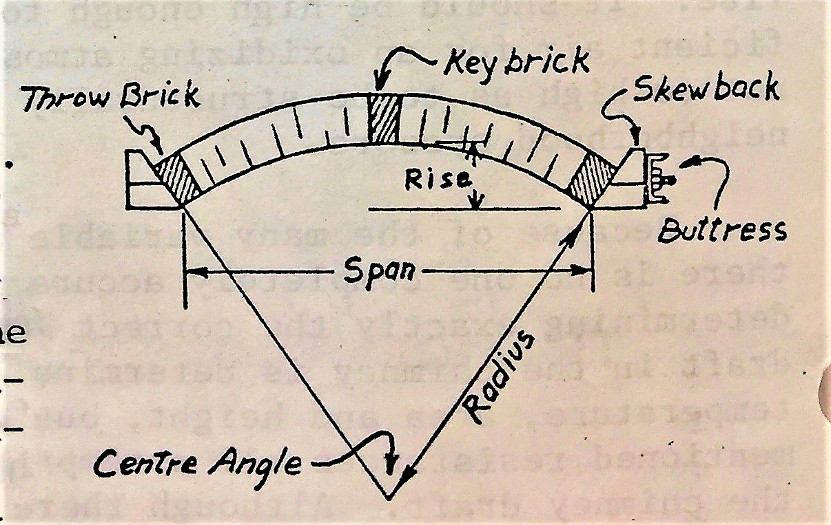
A sprung arch is a portion, of a full circle. The parts of the arch are as shown in the sketch and description. The rise per foot and the span determine all other dimensions.
Arch Form
The wooden form built to the size and correct shape of the inside of the arch to support the arch under construction. It is held temporarily in place with blocks and wedges which are removed when the arch is complete permitting the form to be lowered and removed.
Skewbricks or Skewback
The angled bricks on the top of the side wall which holds the end of the arch.
Buttress
The steel supports which bear on the outside of the skewbricks to support the outward thrust of the arch.
Throwbrick
The first brick in the arch which bears against the inside of the skewbricks.
Keybrick
The centre brick in the arch. Since it is the last brick to be fitted it must be cut to a very close tolerance.
Rise and Span
See Sketch. Number and type of bricks is determined from Mfrs. and arch tables.
Arch Detail
From the brick manufacturers arch tables, we get the following information.
| Span | 46" |
| Rise per ft. | 2.302" (2 5/16") |
| Total rise | 8 13/16" |
| Inside Radius | 2' 10 3/8" |
| Bricks | 7 No. 2 arch |
| 12 No. 1 arch | |
| Total | 19 bricks per course |
For best support, the outer edge of the arch should rest on the top of the wall so we will make the arch l/2" wider on each side than the 45" inside width of the kiln.
THE GAS INPUT
Since the number of burners and the burner port area hinge on the total gas input required, let's look next at means of deciding the gas input needed.
Only a tiny percentage of the gas consumed is used in heating of the wares, there is a huge heat loss. As long as the wares receive the required heat, the losses can vary a great amount, and the potter may not know the difference (except for the cost of each firing). To illustrate this, below is a gas input (BTU) comparison between two actual kilns and the average of the kilns tested.
Note the extreme differences between Kilns "A" and "B". Both are turning out a good product, yet Kiln "A" is doing so with less than ½ of the gas used in Kiln "B". Both are indoor kilns.
Some of the factors determining or affecting the gas input required are:
Size of the kiln,
Coefficient of heat transfer of the walls and roof,
Weight of wares,
Ambient temperature (if outdoors),
Wind velocity (if outdoors),
Kiln atmosphere (oxidizing or reducing),
Draft through the kiln (see "Chimney Height") and overall combustion efficiency.
Because of lack of experience with their new kiln, many potters, if not reaching temperature on their first firing, suspect they are short of gas. This is very seldom the case. we know of one potter, who after firing his kiln for 6 months, now uses one half of the propane per firing that he did when he first started.
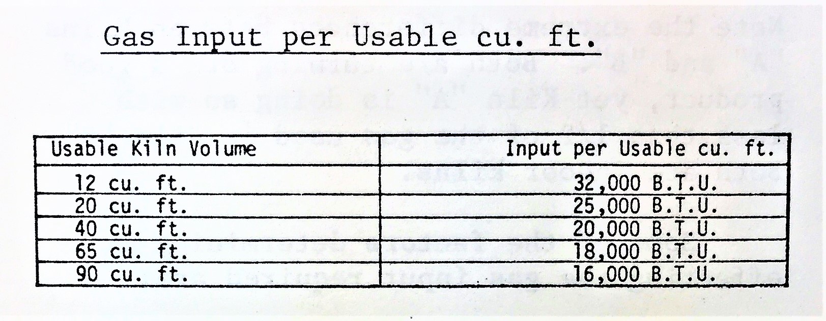
The amounts of gas per usable ft3 vary greatly with the size of the kiln. This can be best illustrated by the Table in Figure 6 which is based on the results of actual tests.
Number of Burners
The "Heritage" type of atmospheric kiln burner is fired at 125,000 BTU on natural gas at 7 in-water-column pressure and on propane at from 11 in-water-column to 2 psi pressure. On propane at 2 psi, one burner can handle 170,000 BTU but one must keep in mind that automatic safety shut-off valves have a maximum rating of ½ psi (14 in-water-column).
Figure 7 - The size of the kiln, the gas input required and the number of burners for Natural Gas and Propane.
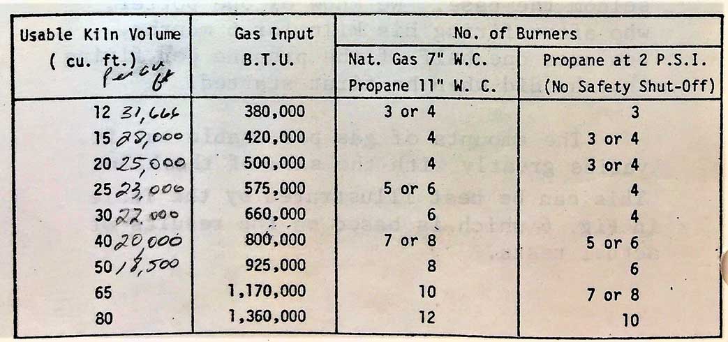
Burners can usually be paired on kilns using 6, 8, 10 or 12 burners and this can cut the cost of automatic safety shut-off in half.
BURNER PORTS
Number and Area
Burner ports may be on the sides or as is preferable, on the front and rear firing parallel with the bagwalls.
The port area can be determined by several methods.
7% of the floor area.
1 in2 for each 8000 BTU gas input.
From the number of burners shown in Figure 7.
For the kiln in this paper, that works out to:
7% of 1093.5 in2 = 76.5 in2 divided by 6 burners = approximately 14 in2.
575,000 BTU input from Figure 7 divided by 8000 BTU = 71 in2 port area which is 12 in2 per burner port.
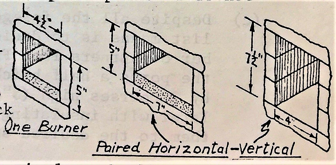
Despite all the foregoing, the simplest means is to decide on the number of burners from Figure 7 and build the ports a half brick wide (4 ½") by 2 courses high (5") and then later with insulating brick, reduce them to the desired size.
Position or Location
About 80 - 90% of kilns have the ports on the sides and 10 to 20% at the front and rear. The size and shape of the kiln room or enclosure sometimes dictates where the ports must be located. Although the gas manifold piping is slightly more complicated by front and rear ports, this position is preferable and should provide somewhat higher combustion efficiency.
Since the burner port is to take air in and not to be a vent outlet; the top of the port should be about 3 courses below the top of the flue exit (see Figure 4). We have seen potters who judged the amount of reduction by the size of the flame (loaded with carbon monoxide) issuing from the top of the burner port. This practice I consider ridiculous and can be dangerous to your health (and Insurance Co.).
Shape of Burner Port
Each ft3 of gas burned requires about 13 ft3 of air for complete combustion. As long as this amount is received; the flame does not really know whether the air is coming in a round or square port. I do not believe the extra work of casting a round port is justified. As mentioned previously, a port a half brick wide by 2 courses high, reduced to the proper area is simple and effective.
When burners are paired as can be done on larger kilns, the ports should be approximately 4" x 7".
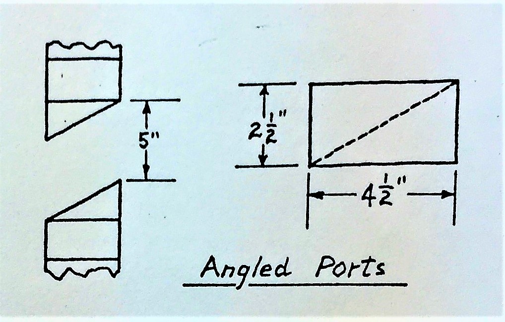
Ports should be angled upward approximately 30° off the horizontal. This can be done in the case of insulating brick by cutting as shown, or where hard firebrick is used, by ordering feather edge bricks.
The Foundation
We have all read that the foundation should go down below frost level. In this area where frost often goes down 8 ft. this is of course impractical. The secret is the drainage beneath the foundation slab and this can be accomplished by a 1 ft. bed of gravel. It should not be located in a low spot in the yard or any area where water may run or accumulate. If there is no other location, an extra deep bed of gravel should be prepared under the slab. As a further precaution to keep the bricks dry a course of concrete blocks could be set on top of the slab to ensure the bricks are high enough to keep dry.
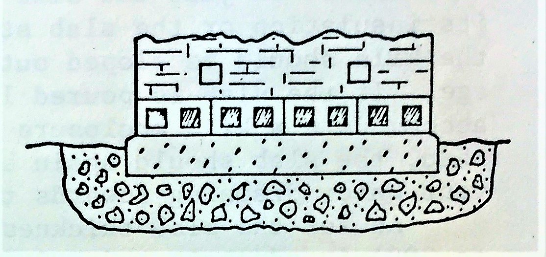
Because of the usual lack of expansion joints in garage floors they are very susceptible to cracking from the heat of the kiln above. Again concrete blocks with the air spaces horizontal are a wise precaution.
If a person is renting a home, it may not be possible to install a concrete slab for a kiln foundation and gas line. We know of one kiln that has stayed perfectly level and sound on concrete blocks which were placed on a well tamped base of sand and gravel.
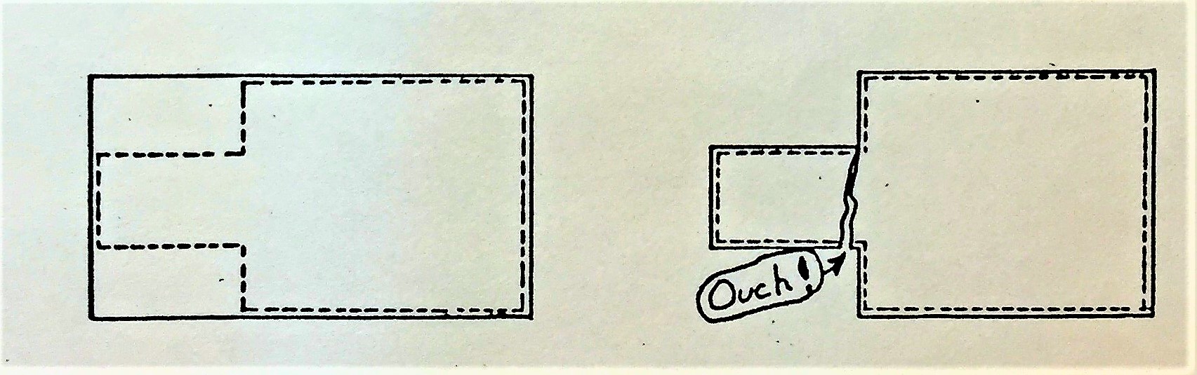
The weight per square inch on the chimney base considerably exceeds that on the base under the kiln so make the slab a full rectangle, as on the left, and don't try to save concrete as on the right, or you could have the chimney taking off on its own like a leaning tower.
On an outdoor kiln, try not to leave any place for snow or water to accumulate. The slab should be just the size of the kiln and its insulation or the slab sticking out beyond the kiln should be sloped outwards for drainage. If the slab is poured large enough to accommodate a kiln enclosure such as a garden shed, the slab should again be sloped to prevent water draining towards the kiln.
As for the slab thickness, 6" to 8" is adequate and reinforcing bars could be placed 1/3 up from the bottom.
A Featherweight Door - Well -- Almost
A Potter once said to me "If I didn't have a brick in the door, I wouldn't feel like a Potter".
However, to many other potters time is money and the time could be more enjoyably or profitably spent at the wheel or elsewhere.
In the past there have been the two alternatives; we must either take the time to brick in the door or else construct a ponderously heavy steel and brick door supported on strong steel supports or rolled on the floor.
The availability of fibrous ceramics has changed all of that and it is now possible to make a close fitting lightweight well insulated door conveniently hinged.
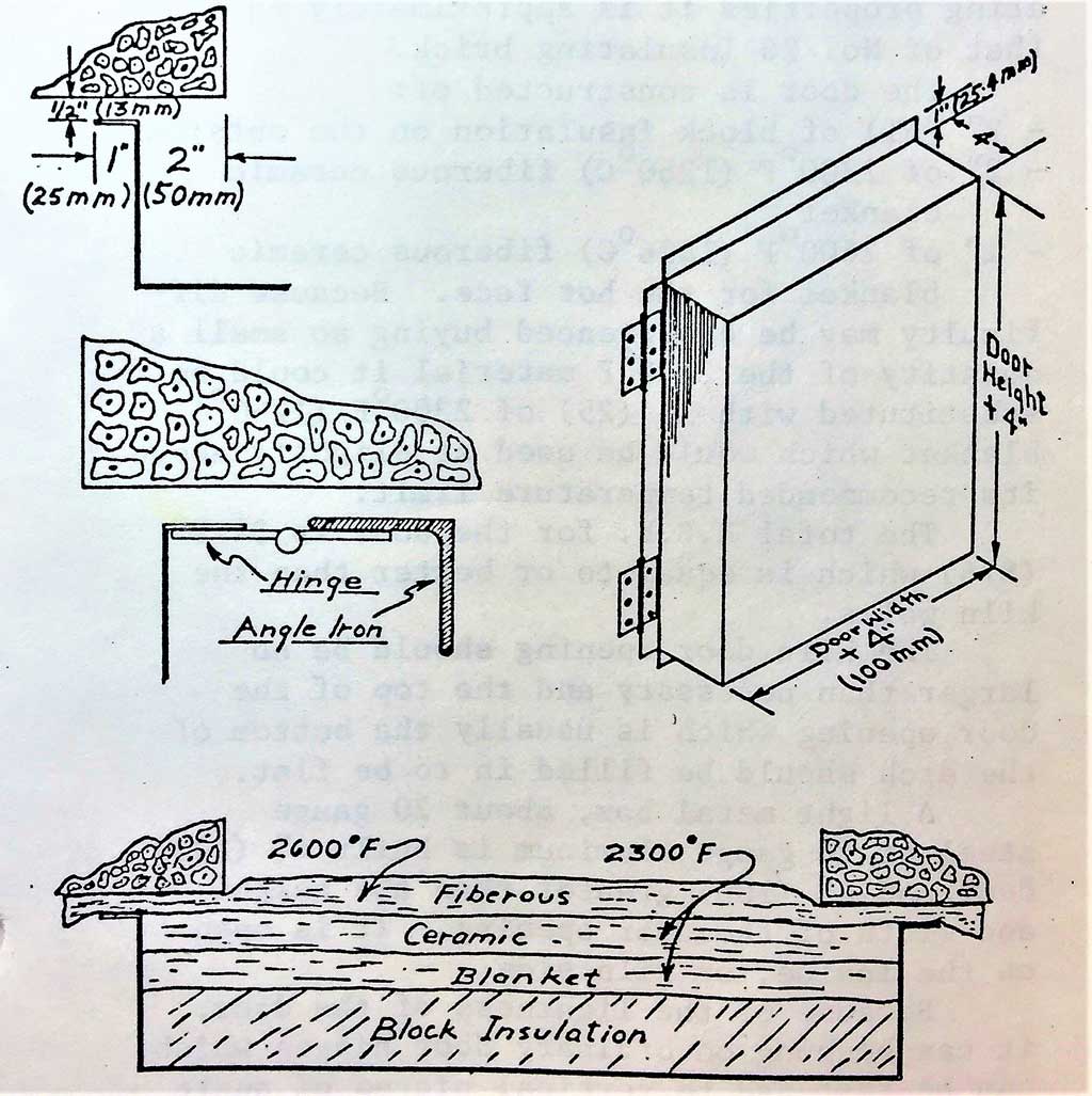
Fibrous ceramic blanket is sold under several trade names. It comes in many forms such as blanket, loose fill, tamping mix and board. It is available with service limits of 2600°F (1426°C) or 2300°F (1260°C). In insulating properties it is approximately equal to that of No. 26 Insulating brick.
The door is constructed of:
2" of block insulation on the outside
2" of 2300°F (1260°c) fibrous ceramic blanket
1" of 2600°F (1426°C) fibrous ceramic blanket for the hot face. Because difficulty may be experienced buying so small a quantity of the 600°F material it could be substituted with 1" of 2300°F (1260°C) blanket which would be used at slightly above its recommended temperature limit.
The total H.B.E. for the door is 34.5" which is equal to or better than the kiln walls.
The kiln door opening should be no larger than necessary and the top of the E door opening which is usually the bottom of the arch should be filled in to be flat.
A light metal box, about 20 gauge steel or 16 gauge aluminium is built 4" deep and 4" greater than the height and width of the door opening. It is open on the inside, or kiln side.
Because of the lightness of the door, it can be hung on ordinary door hinges which can be fastened to vertical pieces of angle iron placed on each side of the door as in
the sketch. Angle iron 2" x 2" x ½" is satisfactory. The hinge on one side and the catch on the other side should be so fitted that the 1" metal flange around the box is held ½" out from the brick.The outside of the box is fitted with 2" of block insulation held in place with firebrick cement or special steel pins. Next comes 2" of the ceramic blanket which fills the box flush with the 1" flange around the box.
Finally to this is cemented one more inch of 2600 F (1427 C) blanket which is cut 4" larger each way than the box. This layer then protrudes 1" beyond the flange; 2" beyond the edge of the box and so provides a sealing surface 3" wide around the door opening. Because the door is spaced ½" out from the brick surface, closing the door squeezes the 1" of blanket to ½" thickness thus providing an excellent seal all around the door.
It must be recognized that since the fibrous ceramic is fragile and subject to wear of loading and unloading, it may be necessary to eventually replace the inside 1" layer. However, that is a small price to pay for the luxury of such a convenient door.
The Setting Floor & Its Openings
The correct sizing and positioning of the floor openings has much to do with obtaining an even firing from top to bottom and side to side. The sketches shown here are for course 5 of the 18 Usable ft3 kiln described later. The same idea however applies to a kiln of any type or size but the number and size of the shelves and the square edge tiles will vary to suit the design.
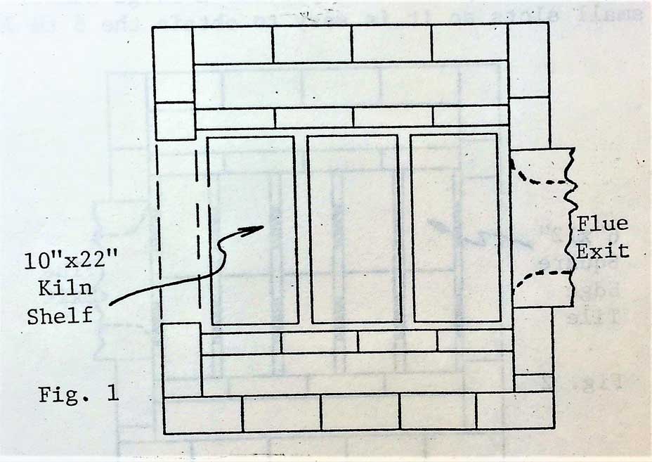
Kiln shelves as in above picture are often used as a kiln floor but it is not usually the best choice; A large number of smaller openings around the shelves is preferable and this can be accomplished by using pieces of broken brick or shelves. Our survey of kilns found the best performance with the area through the floor reduced to 6 or 7% of the floor area.
The better choice for a good floor is to use square edge tiles or standard hard firebrick depending on the size of the kiln.
Square edge tiles are intermediate duty hard firebricks which are cast in various sizes and available 2" or 2½" thick in the following sizes.
6" x 12 " |
9" x 12" |
12" x 12" |
6" x 18" |
9" x 18" |
12" x 18" |
As the below image shows, the 6" x 12" square edge tiles work out very well and provide a large number of small slots so it is easy to obtain the 6 to 7% floor opening area. It will probably be found preferable to have the openings a little larger at the front where the draft is least and smaller at the rear closer to the flue exit where the draft is greatest. 'Another advantage of the square edge tile is that the cost is about one-quarter that of kiln shelves.
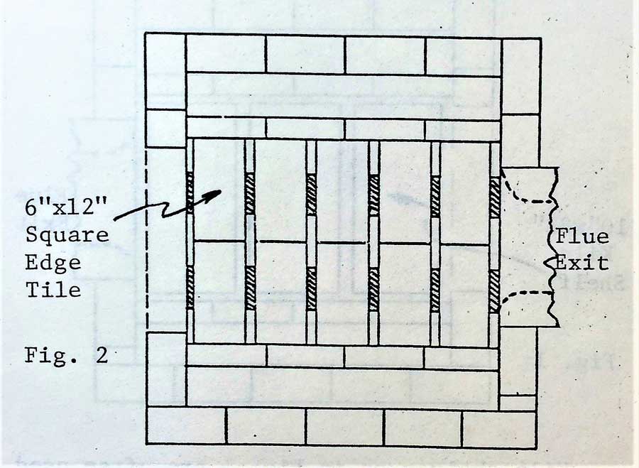
Arches
The question is often asked, which is best, a catenary arch or a sprung arch. In testing scores of kilns, it has been my experience that performance wise, there is no difference worth considering and there are several more important factors which decide the worth of the kiln. If the port area, floor opening area, combustion space, flue exit area, chimney height and area, bagwall position and height, flue in-put, and ware stacking are all correct; the type of arch matters very little.
The difference then comes down mostly to construction and there are pros and cons on both sides of the fence so you are the judge.
A sprung arch kiln if of a 4½" brick wall with block insulation needs steel corner supports as well as a steel buttress. With a 9" brick wall the only steel necessary is the buttress. A catenary arch kiln needs no steelwork whatsoever.
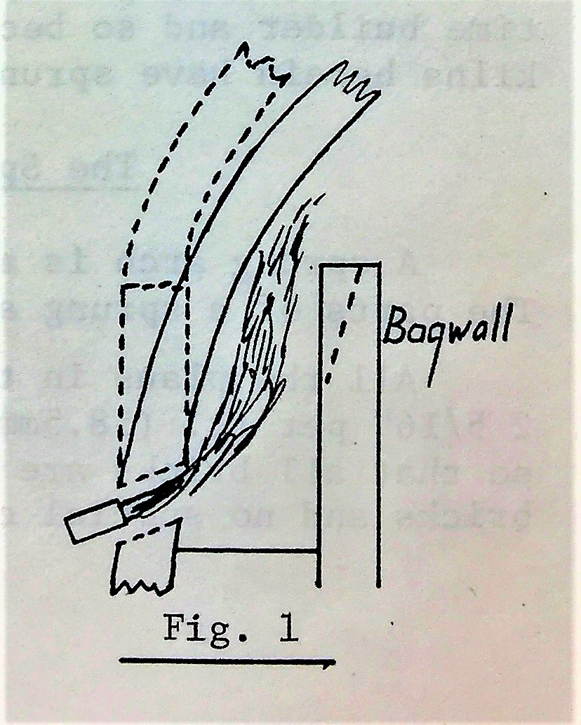
A catenary arch kiln, because of the inward sloping walls may have a tendency to overheat the wall opposite the top of the bagwall and reduce the stacking space higher up. This however can be partially overcome by sloping the top outside of the bagwall as in above image or by building the wall straight for a few courses before starting the arch.
The combustion area in a sprung arch kiln is of a constant width because of the vertical wall as in following image.
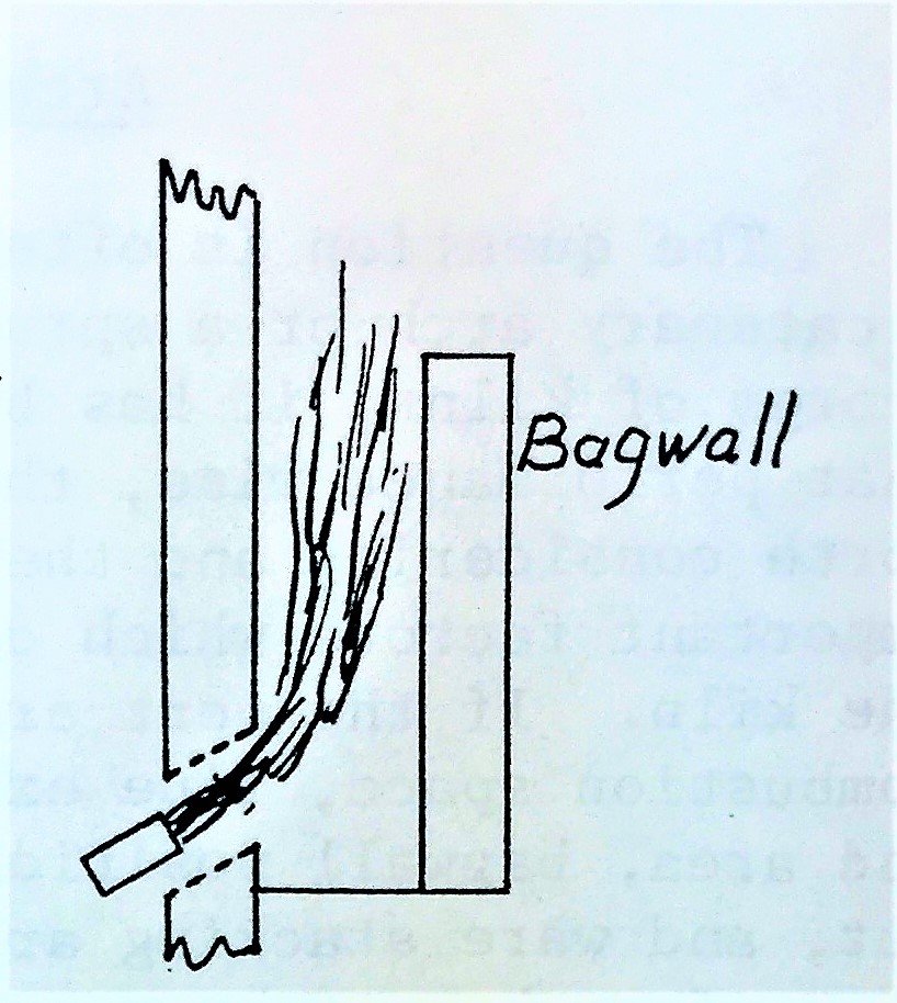
A straight sides, sprung arch kiln can be built with all standard bricks and the number of each type of brick can be easily worked out ahead of construction. A catenary arch has an ever changing angle and presents more problems for the first time builder.
A well-built catenary arch kiln is a thing of beauty and a potter once told me that he wouldn't feel like a potter without a catenary arch kiln.
This "nitty gritty" book is for the first time builder and so because of the simplicity, kilns herein have sprung arch roofs.
The Sprung Arch
A sprung arch is a portion of a full circle. The parts of a sprung arch are shown in the following image.
All the plans in this book have a rise of 2 5/16" per ft. (58.5 mm per 300). This is done so that all bricks are standard purchasable bricks and no special cutting is necessary.
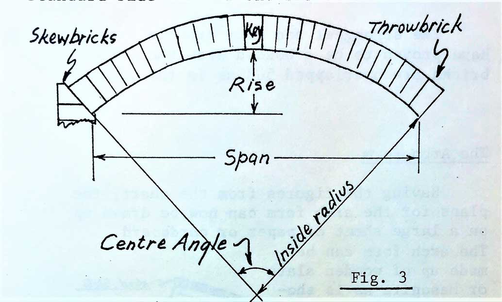
It means that the skewbacks can be made of a standard side skew or end skew. This is not Centre so important where easily cut insulating bricks are used but is very important with hard fire bricks which the inexperienced person find difficult to cut or break.
When the kiln has been designed and the inside width of the kiln is determined, the arch can be planned. For extra strength the throwbrick, (the outside brick of the arch) should be sitting on top of the wall about 3/4" to 1" back from the inside edge of the wall as in the following image. Because of this, knowing the distance between the inside walls, add 1½" or 2" to that to determine the span of the arch.
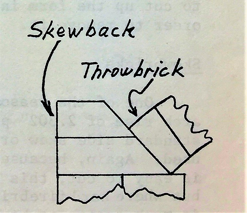
From the chart at the end of the chapter find the span and then read across to deter mine the rise, inside radius and the number of No. 1, 2, 3 or straight bricks in each row. As in all kilns herein.
The strongest and most trouble free arches have proven to be a bonded arch where the bricks are overlapped 50% as in the walls.
The Arch Form
Having the figures from the chart, the plans for the arch form can now be drawn up on a large sheet of paper or cardboard. The arch form can be made up of wooden slats or Masonite as is shown in following image.
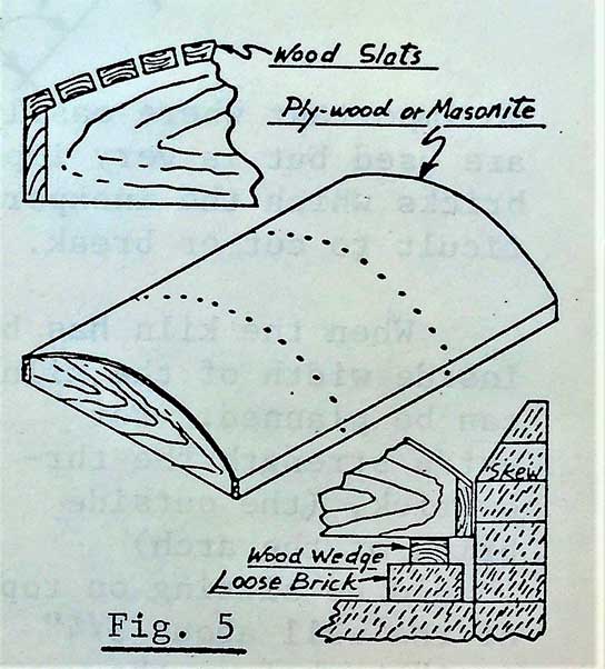
Be sure to place the form on wedges so that it can be dropped about 2" for removal. As we have seen, failing to allow enough space can mean having to cut up the form in order to remove it.
Skewbricks
One of the reasons for choosing an arch rise of 2.302" per ft. is that a standard side skew or end skew can be used. Again, because insulating brick is easy to cut, this is not a problem, but where hard fire brick is planned it is much easier to be able to purchase them.
An alternate but less satisfactory type of Skew bricks is as shown in following image.
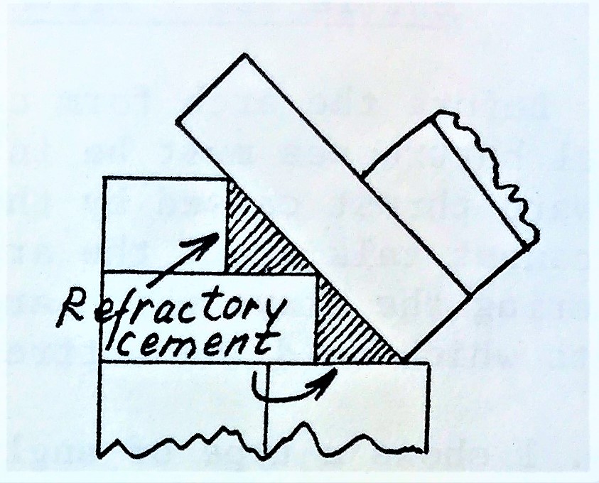
Hard Firebrick Arches
To build an arch of hard firebrick one is wise to purchase the No. 1, 2 or 3 arch bricks. However some potters are fortunate enough to find free used bricks and so wish to fuse them in the arch as well as the walls. Though not quite as satisfactory, it can be done and in this case, the wedge shaped gaps between the bricks are filled with refractory cement and bits of broken pottery as in following image.
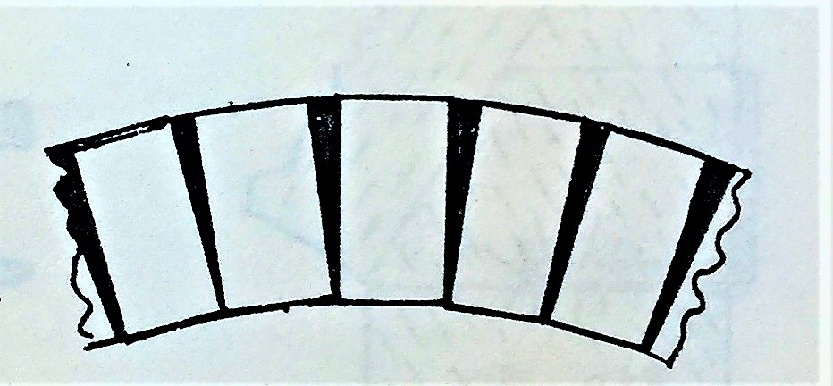
Buttresses - Prevent Fallen Arches
Before the arch form can be removed the steel buttresses must be in place to take the outward thrust caused by the weight of the arch. We cannot talk about the arch without also considering the stays which are the threaded bolts which hold the buttresses together.
The following image shows a type of angle iron buttress which is quite common but which has an inherent danger of overheating the inside portion of the angle iron. This weakens the buttress and I have actually seen an arch which dropped slightly at the centre because the angle iron bent outwards when the kiln was hot.
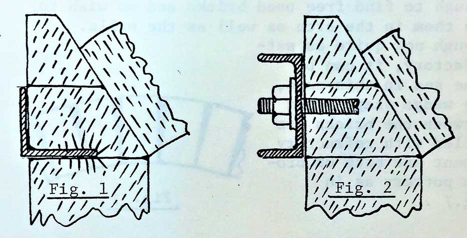
Although slightly more costly, I am a firm believer in a buttress of 3" or 4" channel iron as in above image.
An average size kiln having a 9" wall thickness does not always need any angle iron corner supports and may only need a channel as the buttress. The problem here is that the front stay is in the way of loading since it is several inches below the bottom of the arch as in following image.
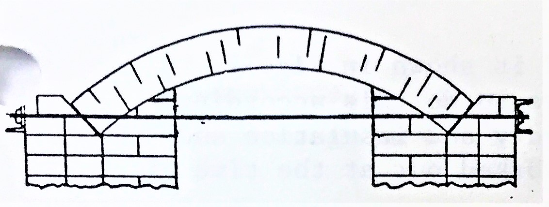
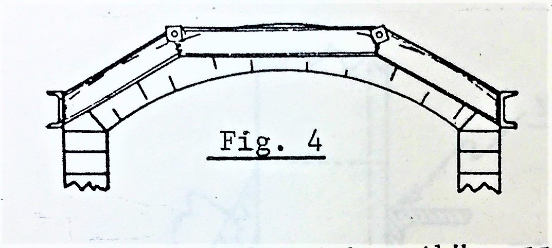
In a kiln with a 4½" wall one is certain to need angle iron corner supports so the method shown in following image is very popular and works well. To prevent being bowed outwards from the Expansion of the arch when the kiln is hot, the supports should be quite substantial such as 3" x 3" x ¼" and the stays should be as close to the top of the arch as possible.
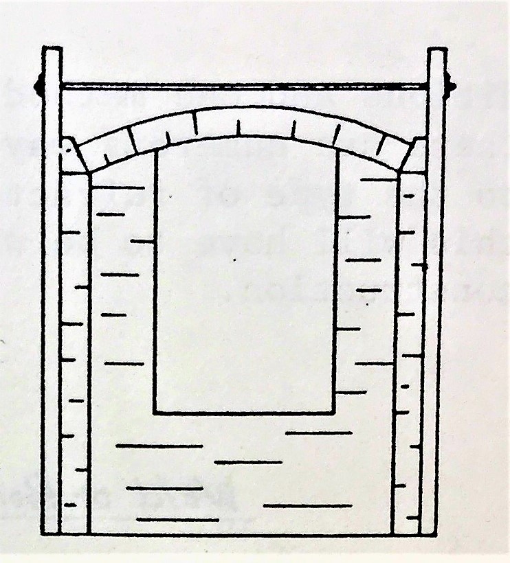
As in following image, the above mentioned angle iron corner supports must be outside the insulation to prevent warpage from the heat.
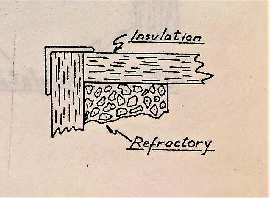
Since the vertical supports are outside the insulation but the buttress must be firmly against the brick skews, provision must be made to accomplish both conditions and one method is shown in following image. There are numerous ways to do this according to the type of refractory and insulation and this will have to be worked out at the time of construction.
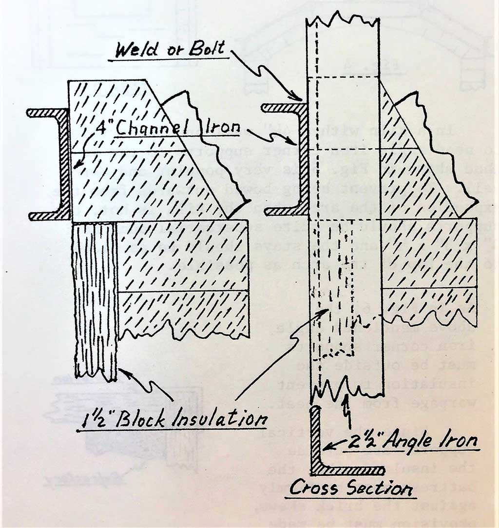
A kiln of about 18 to 20 usable ft3 has proven to be very popular and an excellent size for many potters. It will supply the needs of a large percentage of potters who supplement another income and even some who depend on it for a living.
The design and construction has been kept as simple as possible but if properly built, it will be able to fulfil the potter's wishes for top quality firings, with the desired atmosphere, in safety and with as reasonable efficiency as possible.
Here is a kiln plan to do just that, but yet leave flexibility in construction materials, burner port position, kiln floor, etc. as desired by the potter.
This kiln is not new or different. It is a good basic simple design that has proven itself satisfactory for many potters over many years. Its proportions are ones that have been accepted for many years and has shown excellent performance in our tests of numerous successful kilns.
The setting floor is 24" wide by 36" deep with an inside height of 38". For those desiring a slightly larger kiln, increasing the height by 5" by the addition of 2 courses of bricks will bring the usable capacity to 20.5 ft3.
The kiln shelves used are 10" x 22" or depending on the manufacturer may be 10½" x 21".
Plans are shown for the burner ports to be located on the sides, firing at the bag wall or, on the front and rear with the burners firing parallel to the bag wall, which is somewhat preferable.
The Sprung Arch has a rise such that standard arch bricks are used and the skew bricks are a standard side skew. This is not so important where easily cut insulating bricks are used but is most important for hard firebrick.
Building materials are open to choice. By far the most popular has been 4½" of No. 26 Insulating Firebrick insulated with 1½" of 1900°F block insulation. It provides a wall only 6½" with a hard brick equivalent of 32.4" and is the easiest to build for the first time builder. Second and third choices have been No. 26 with No. 20 insulating firebricks; and hard firebrick insulated with No. 23 insulating brick.
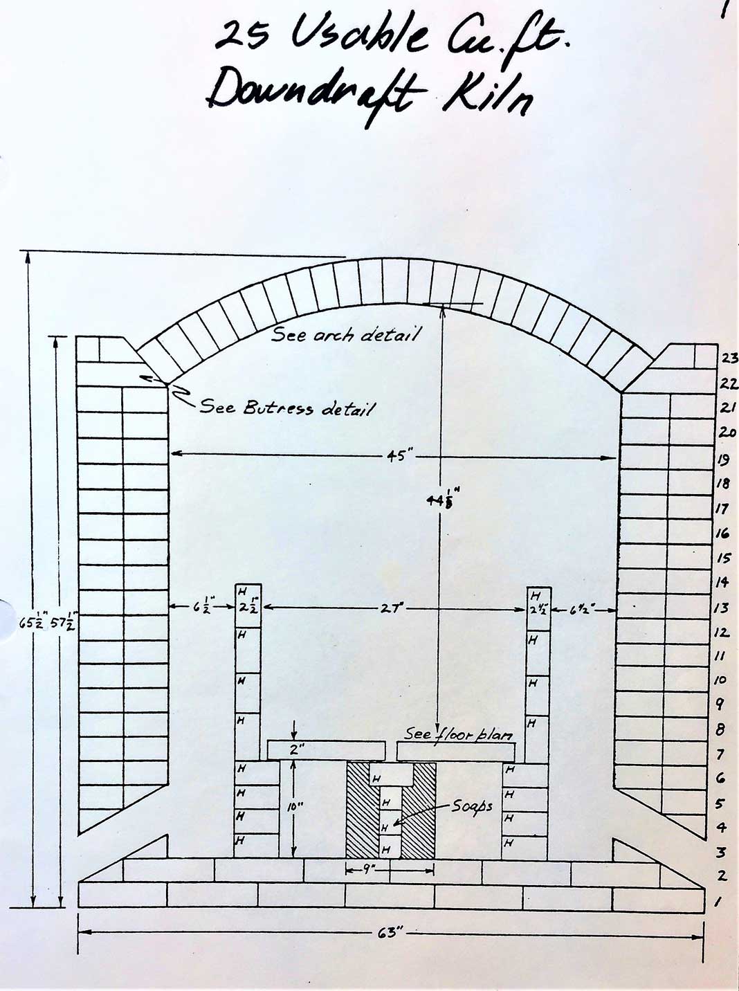
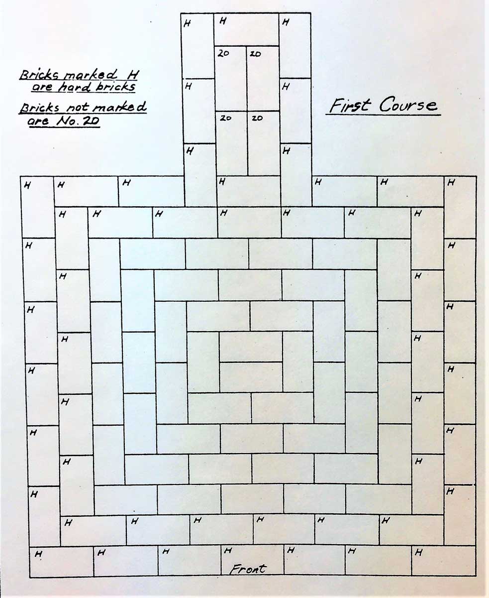
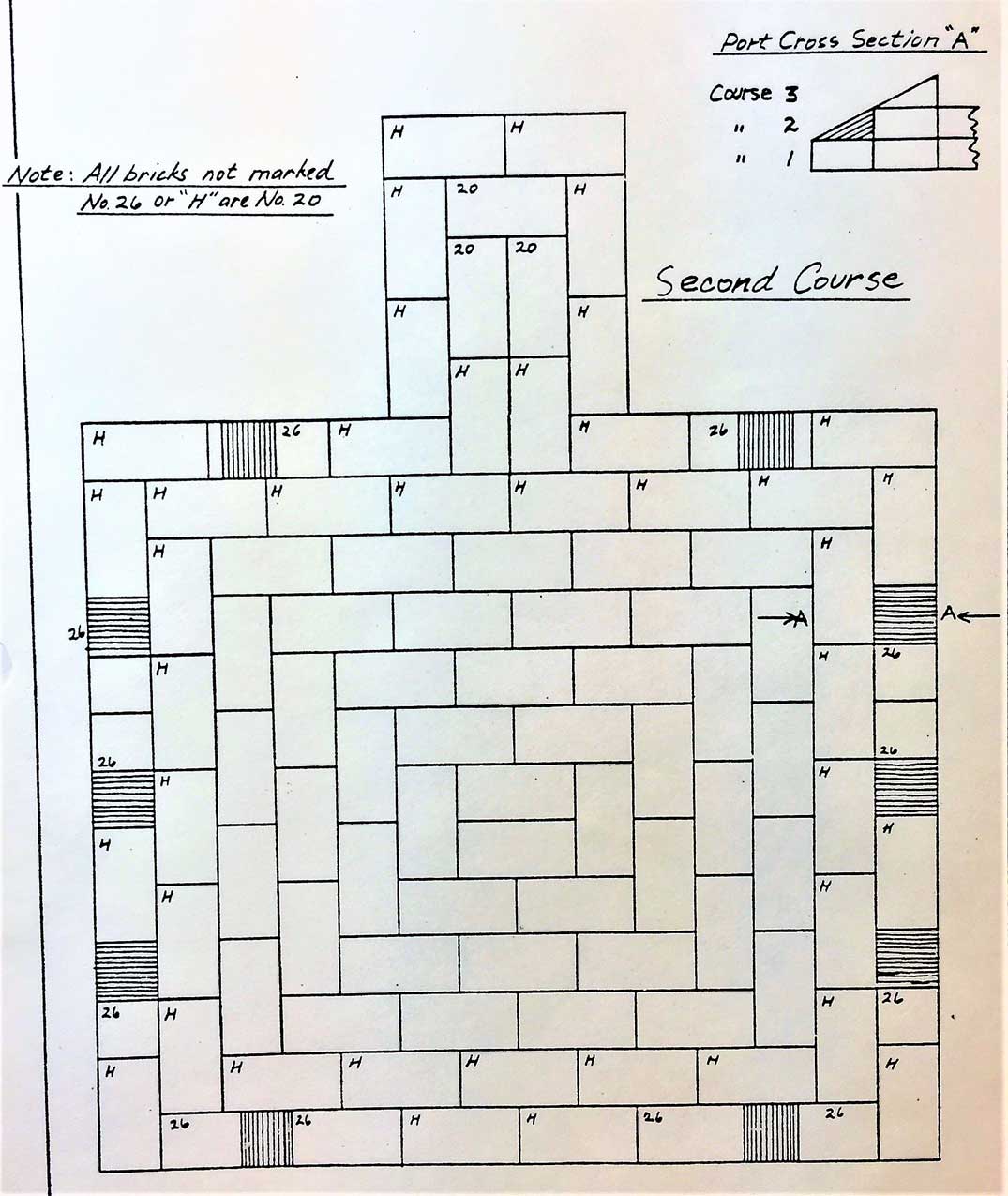
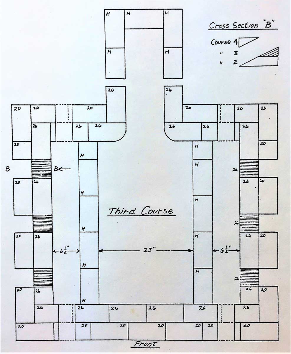
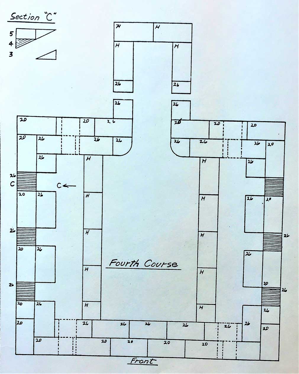
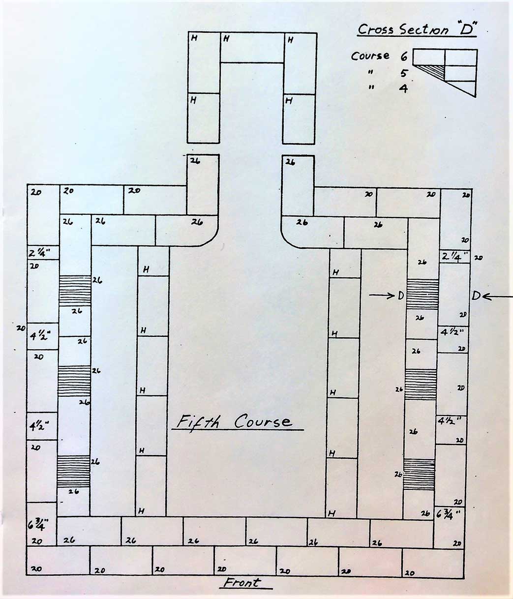
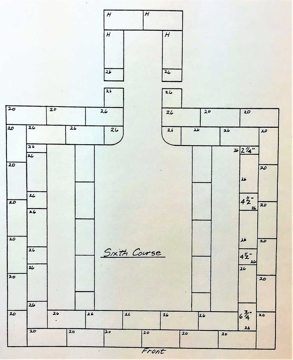
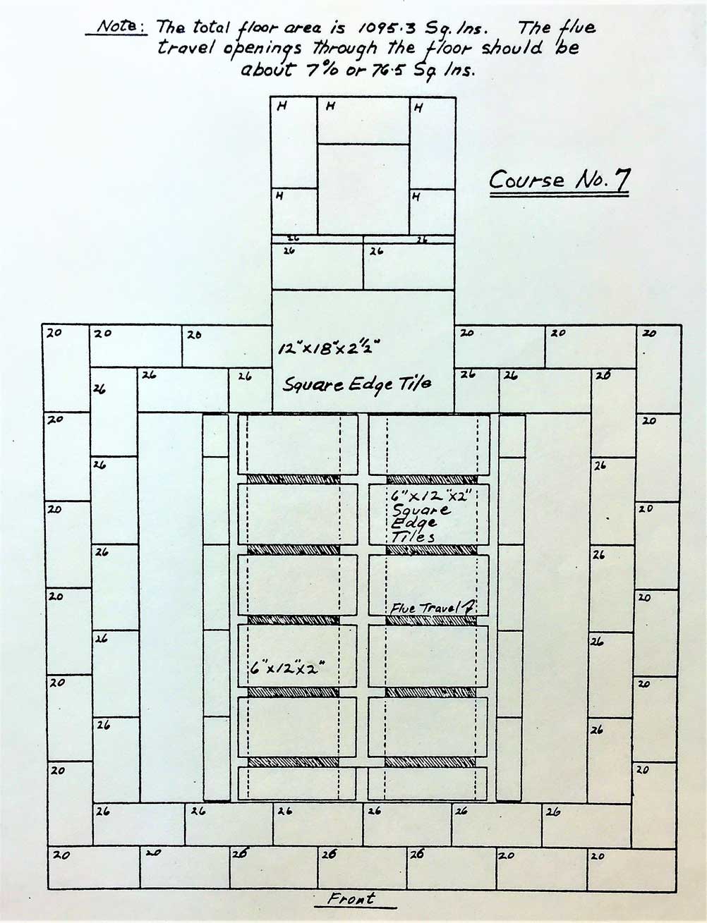
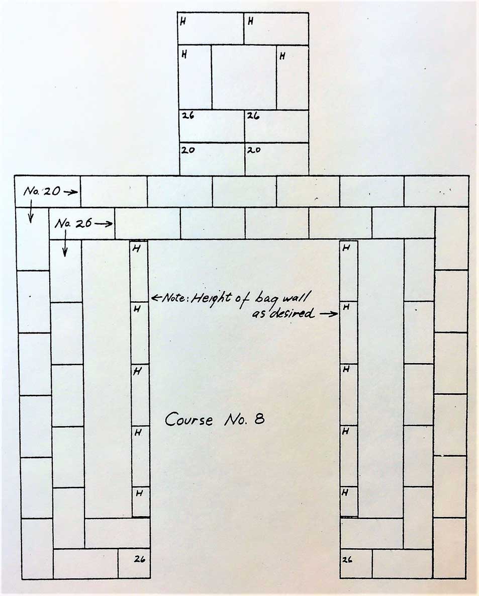
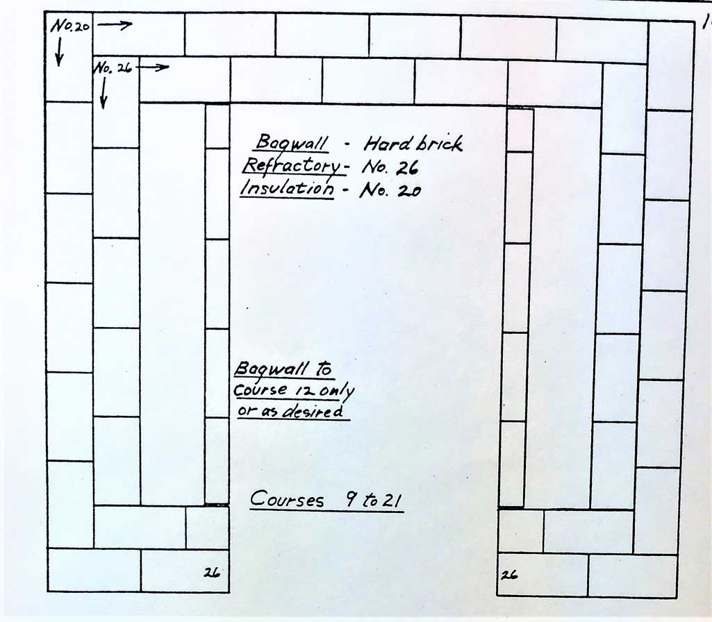
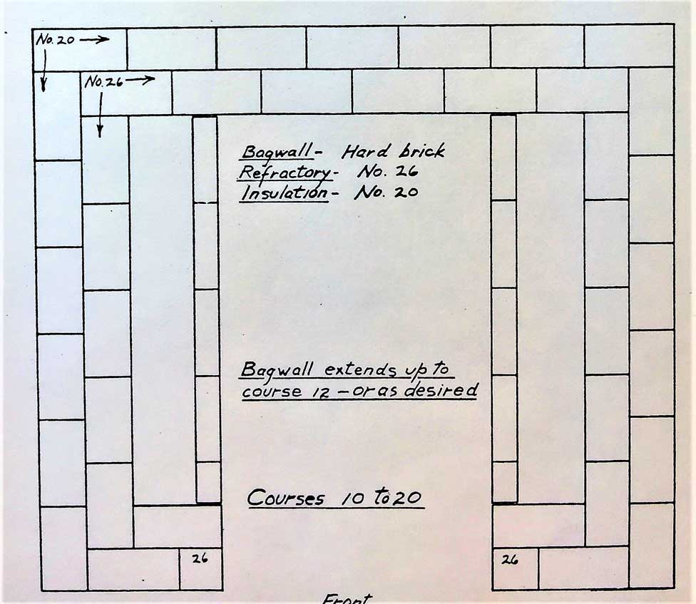
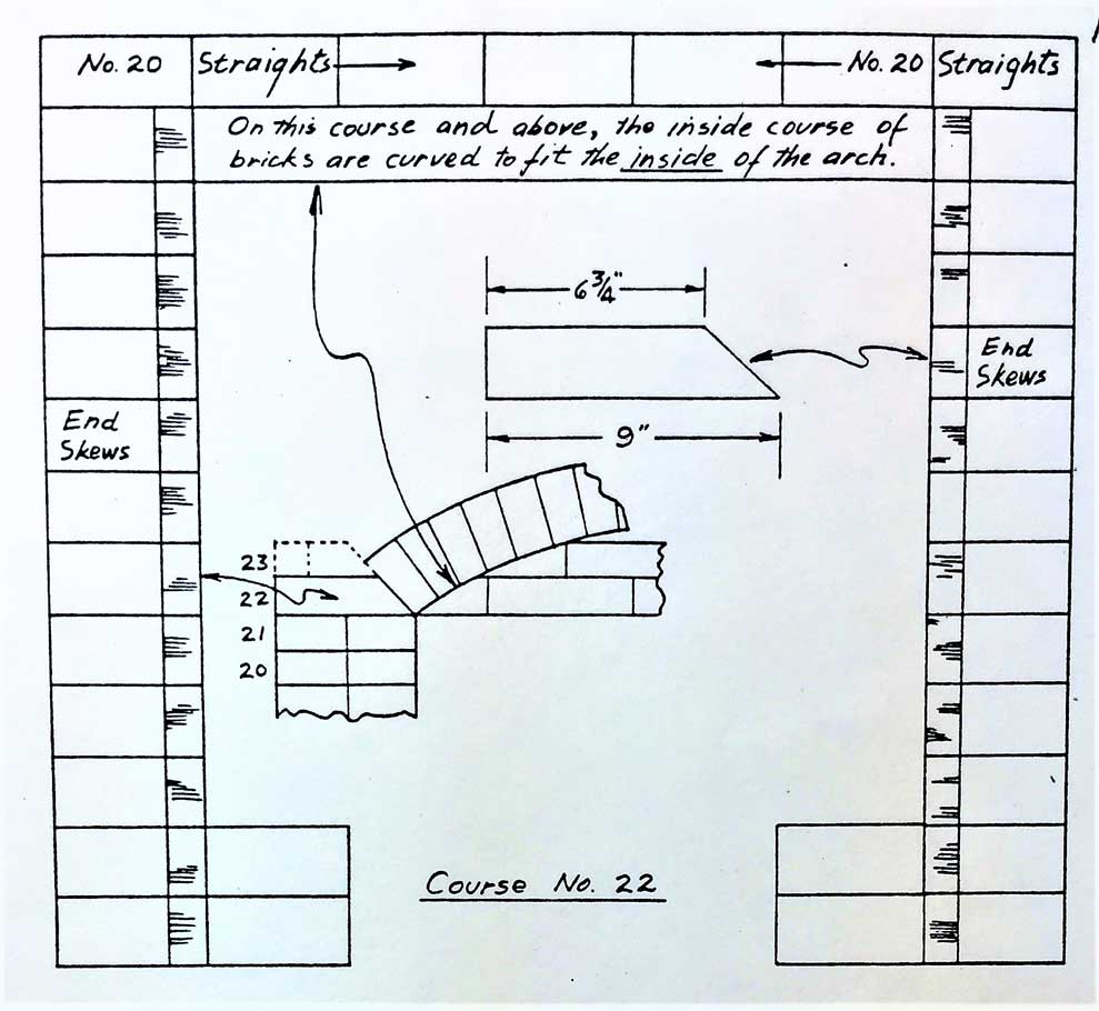
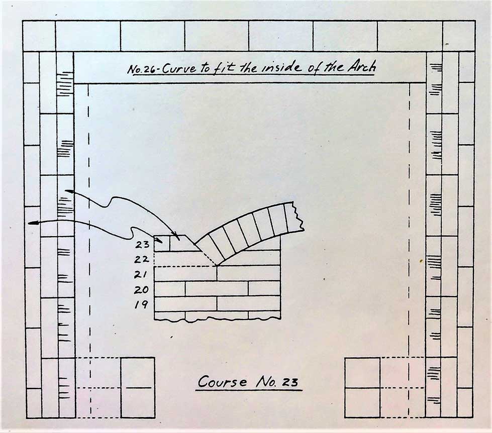
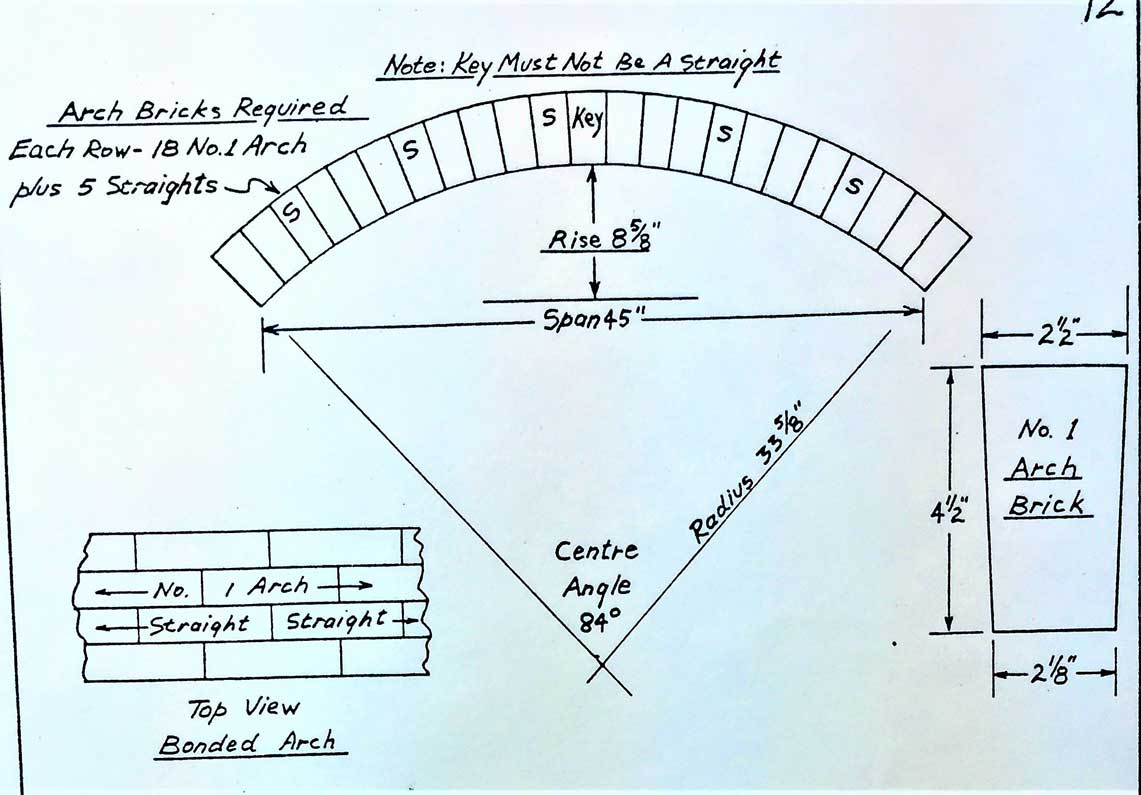
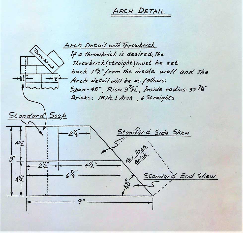
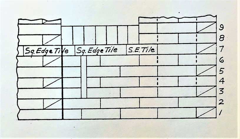
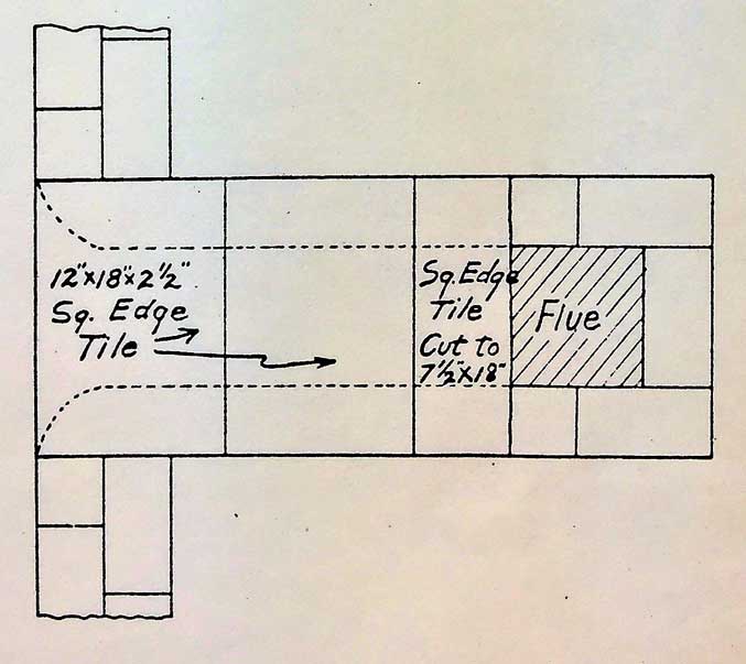
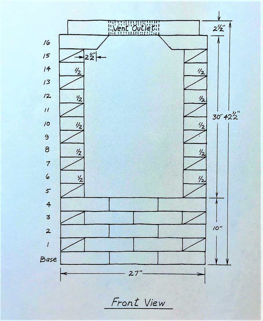
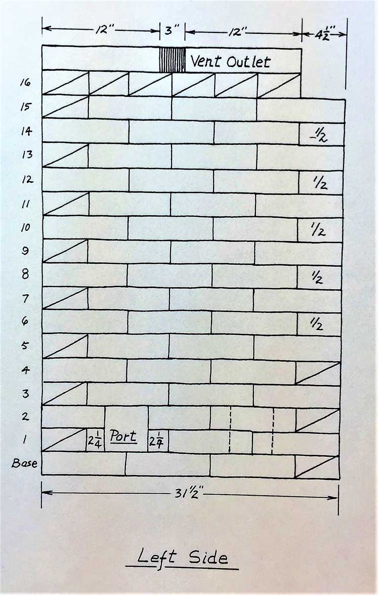
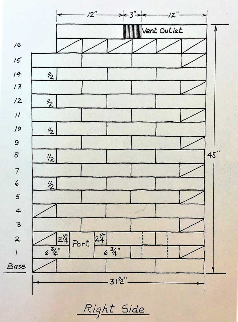
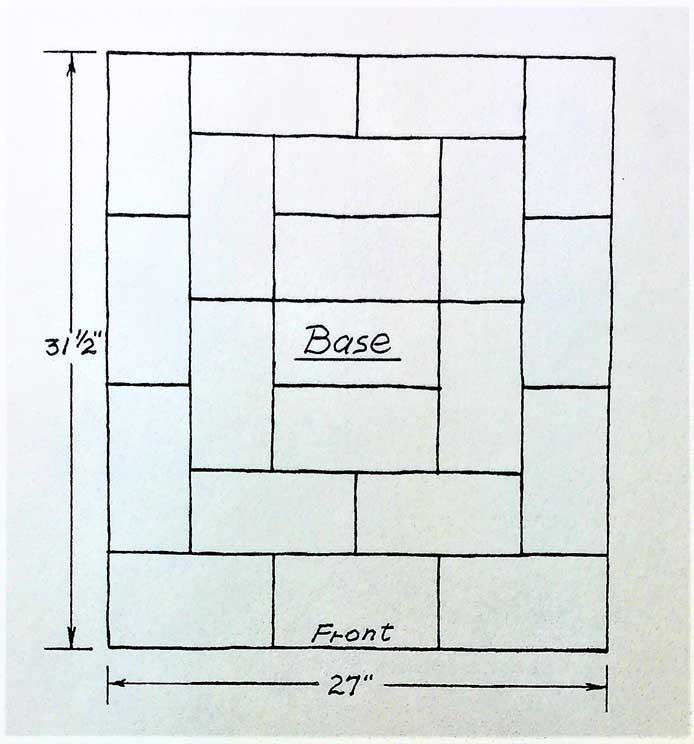
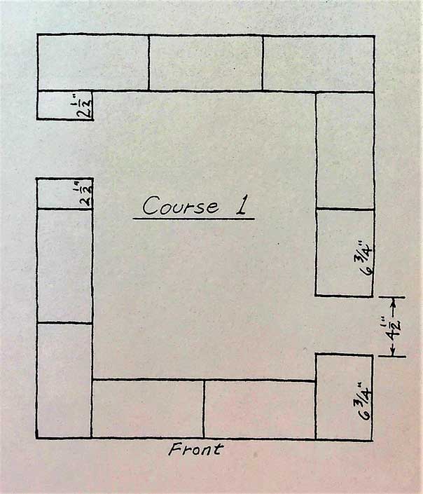
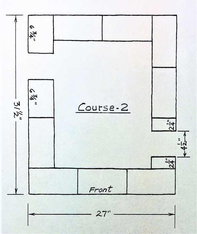
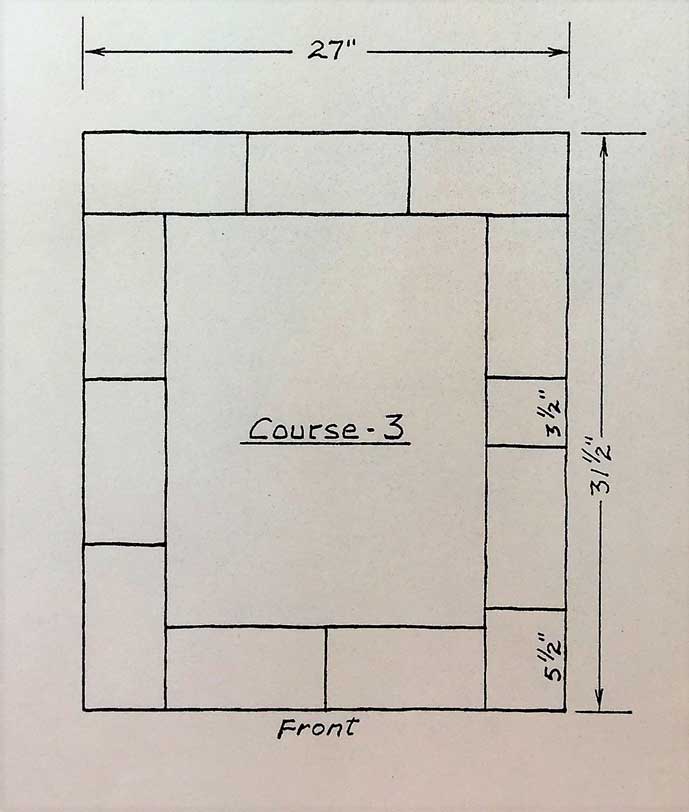
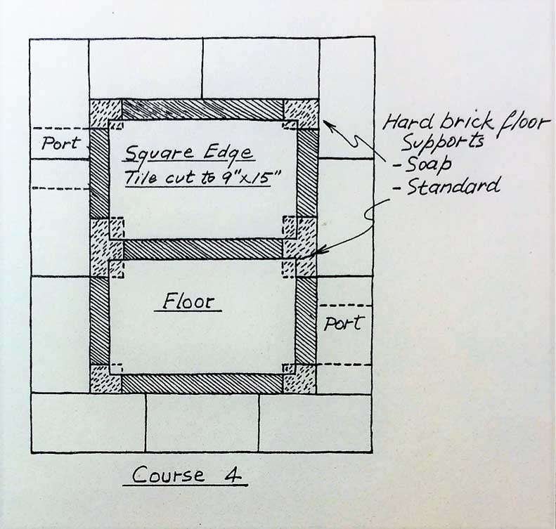
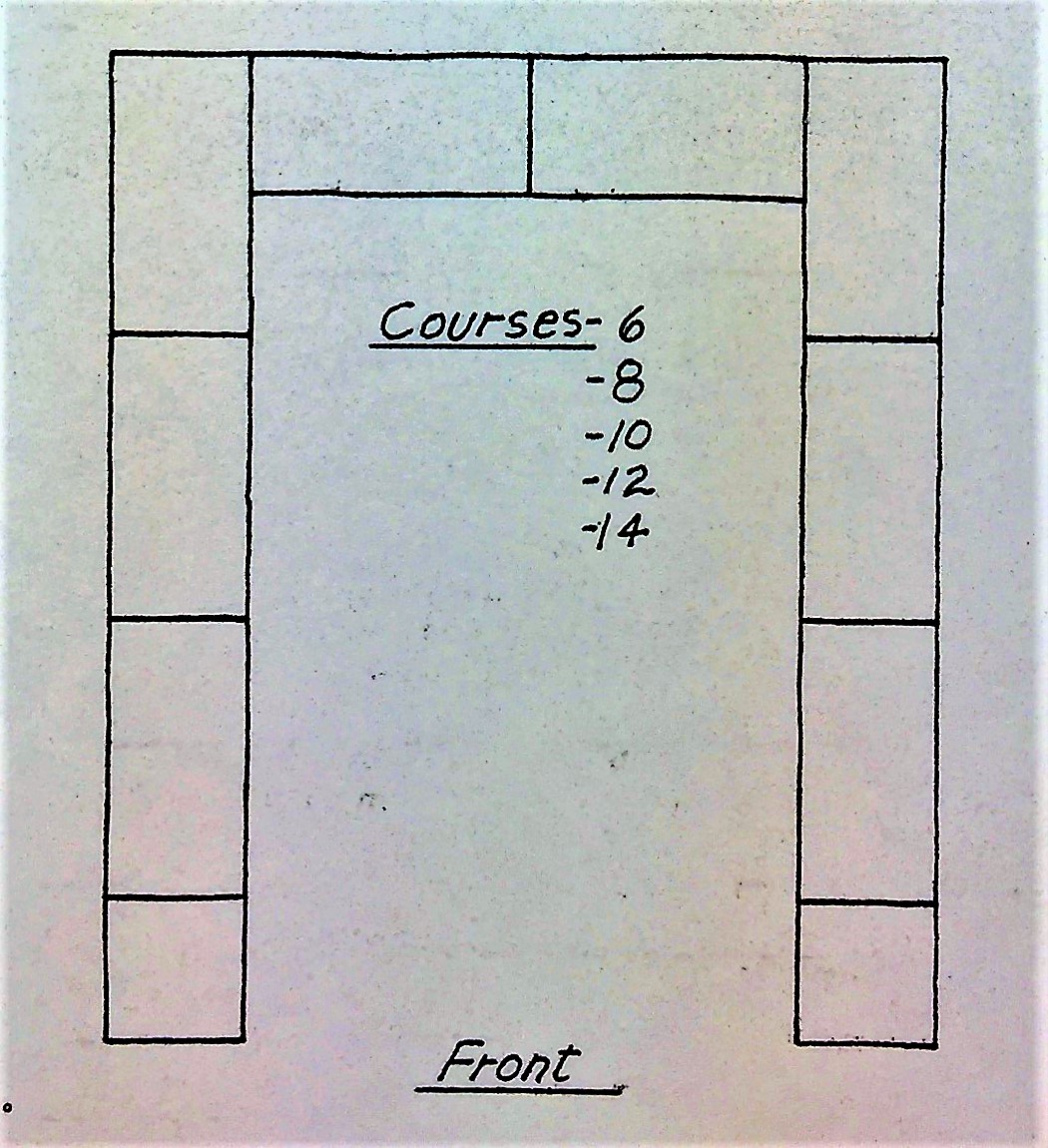
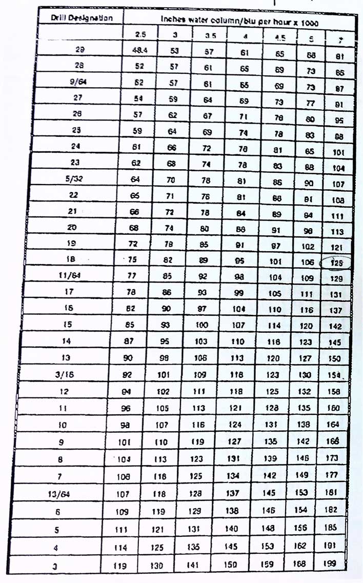
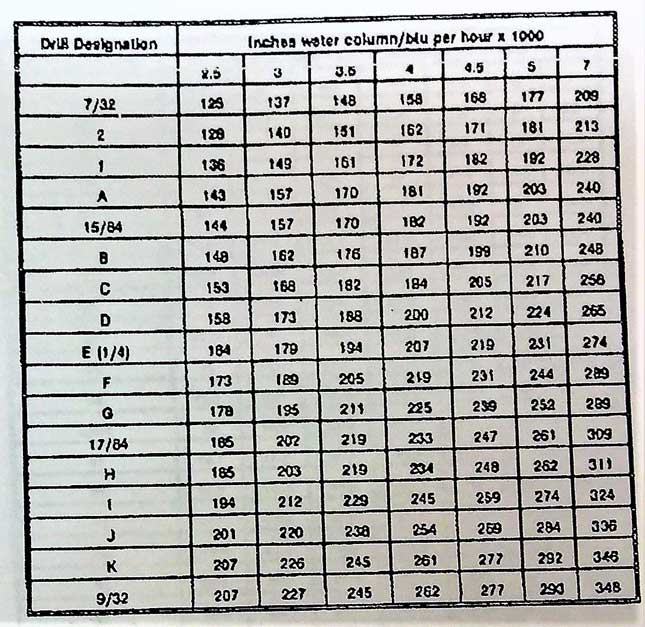
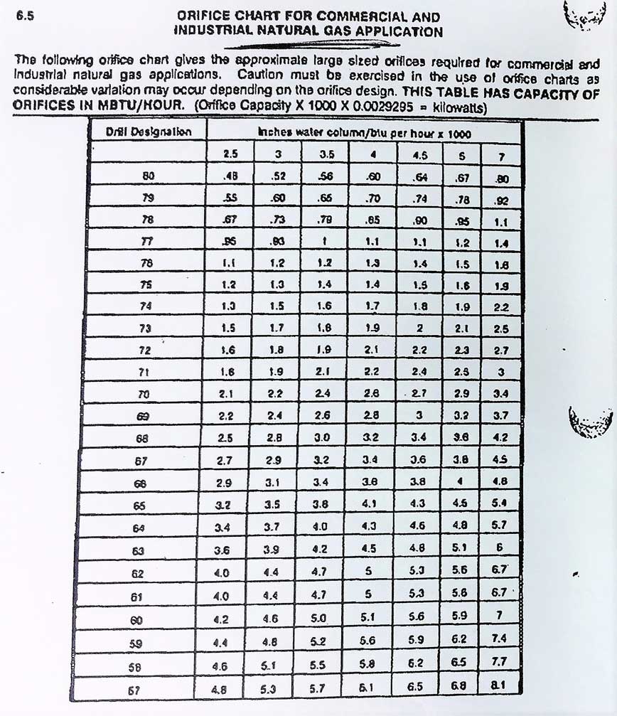
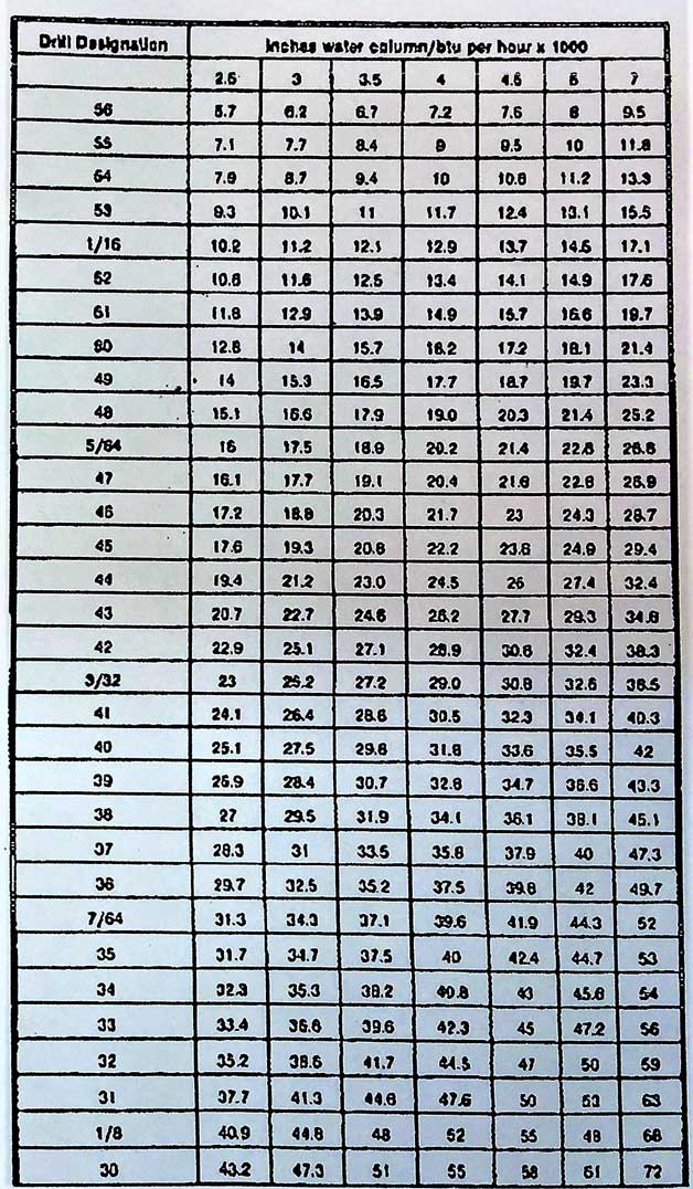
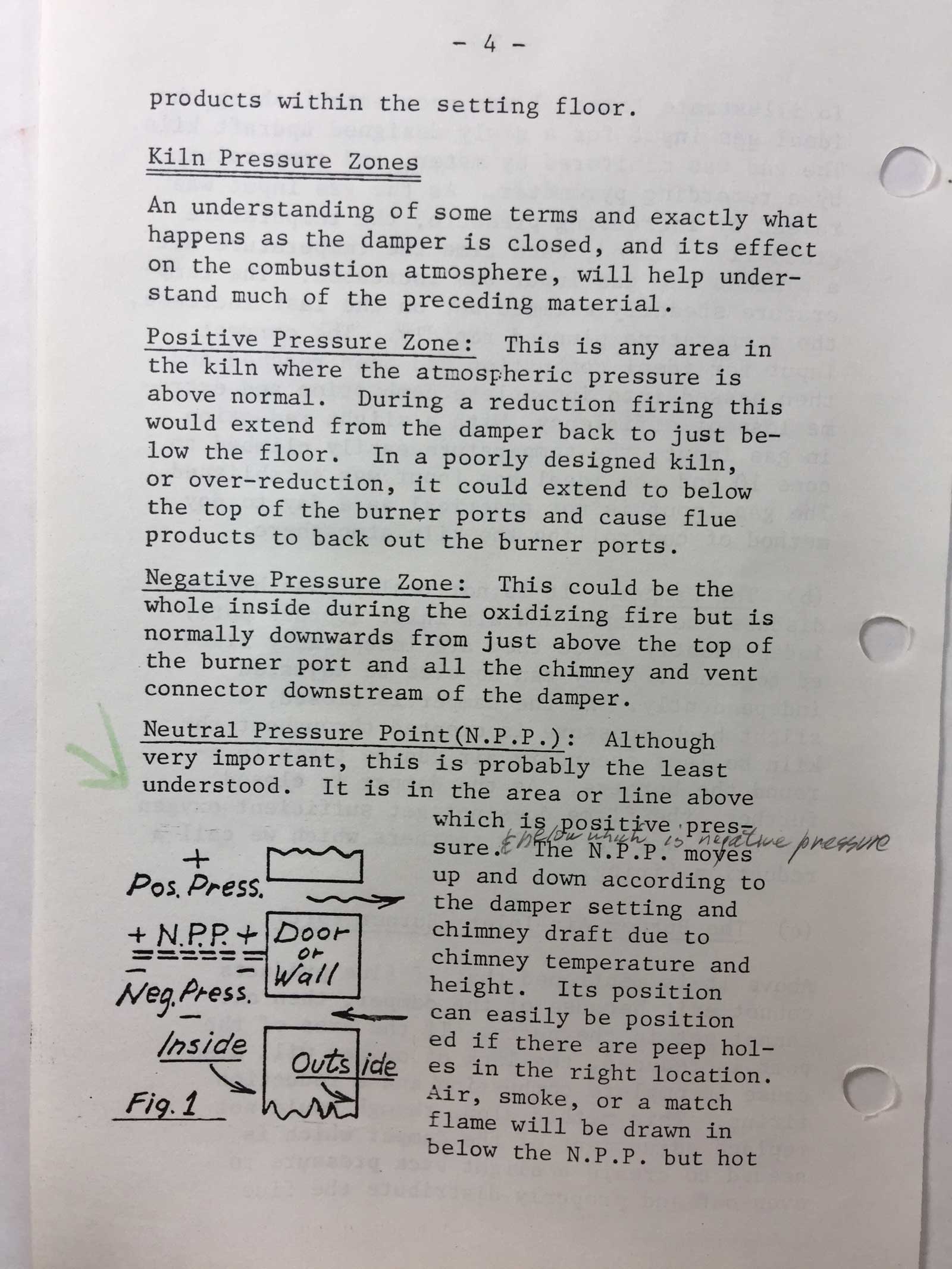
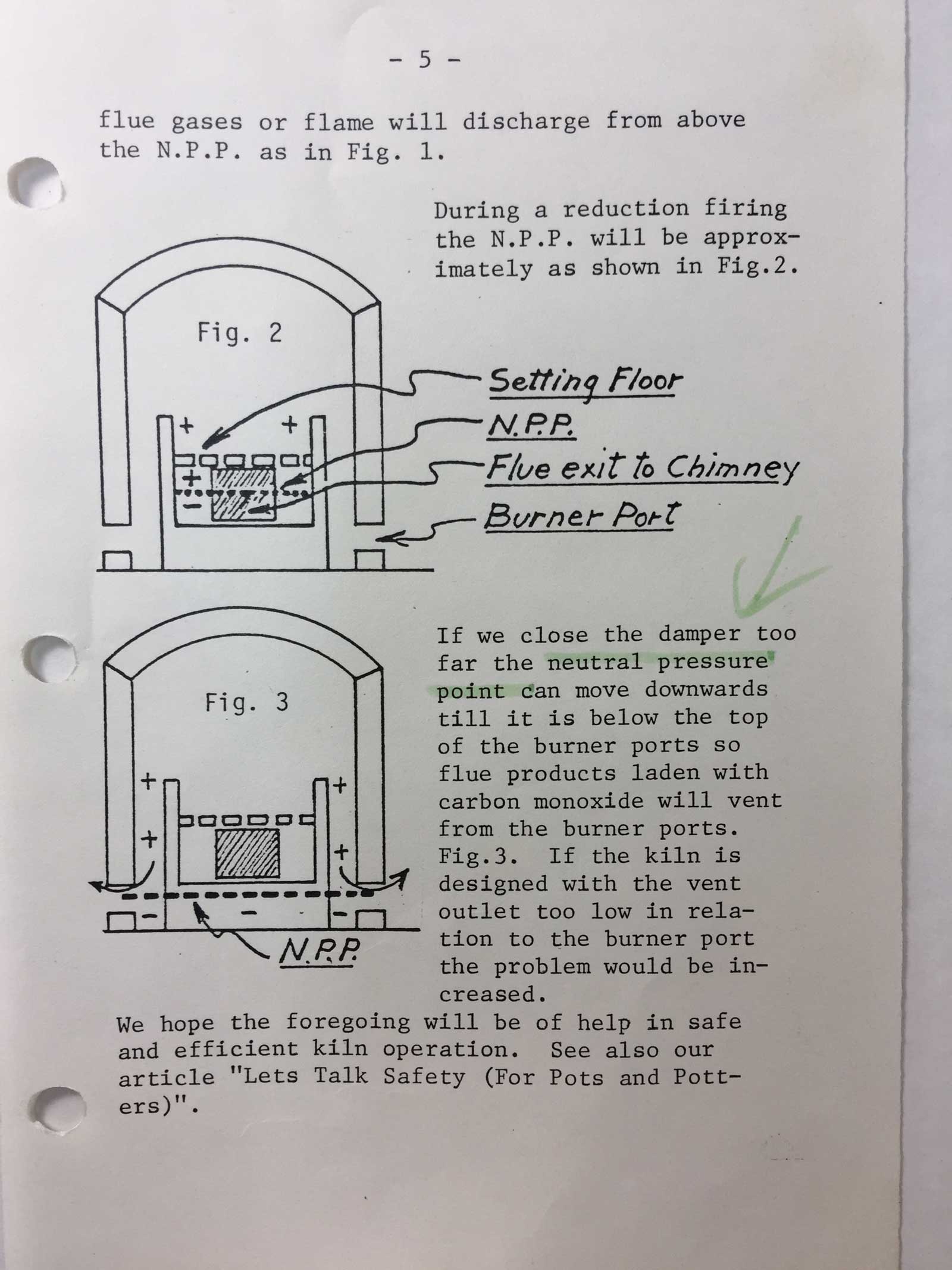
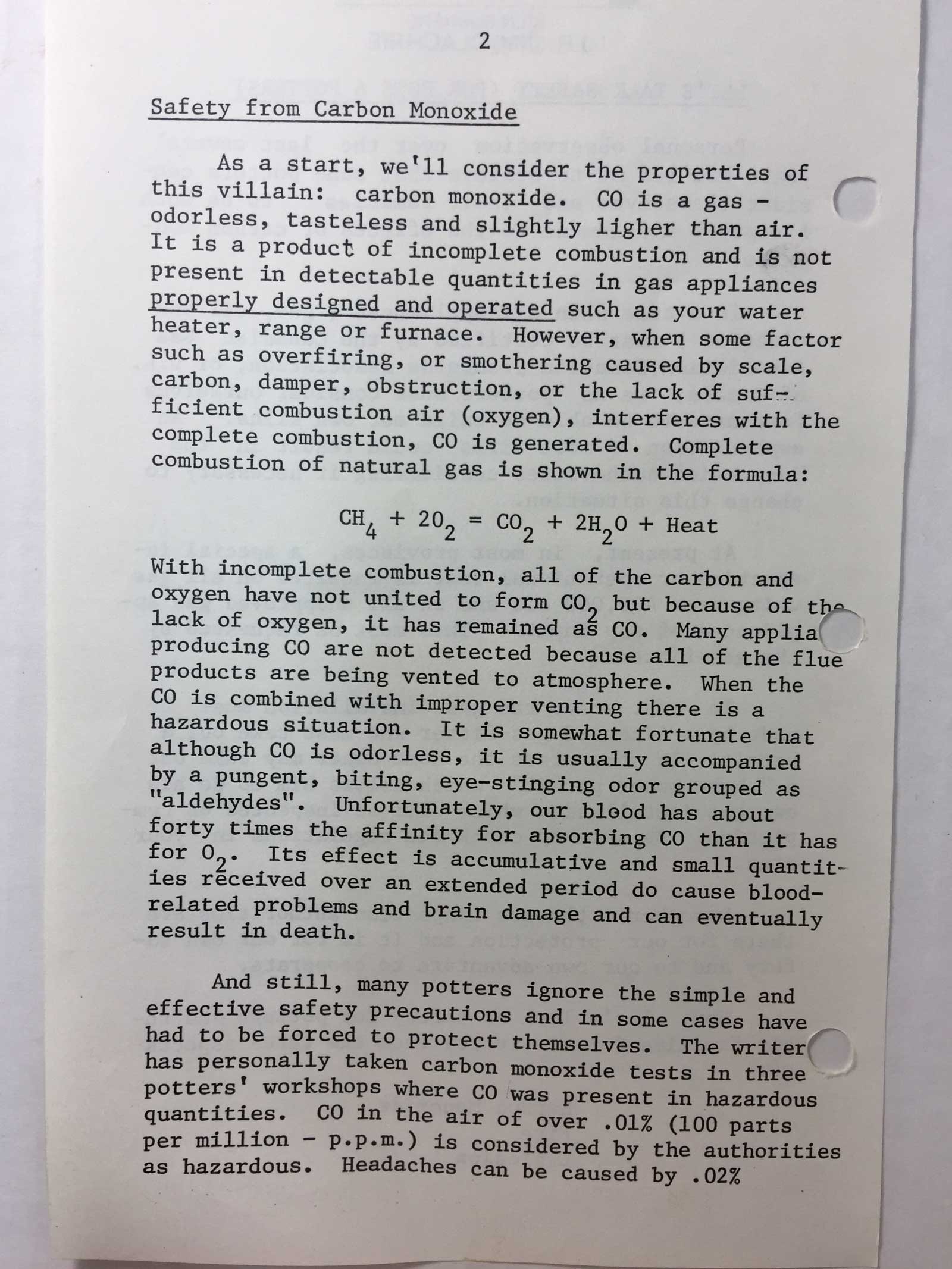
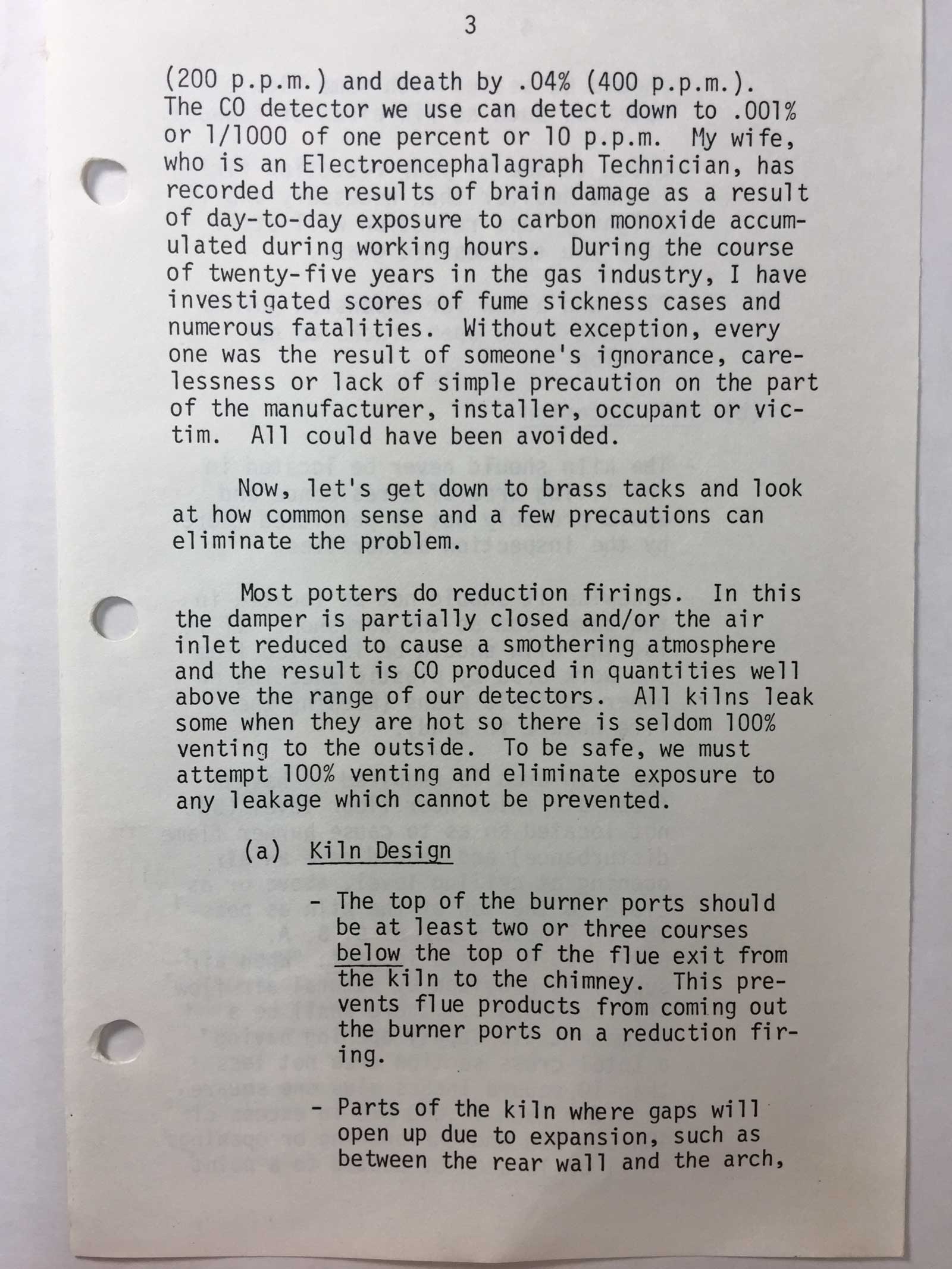
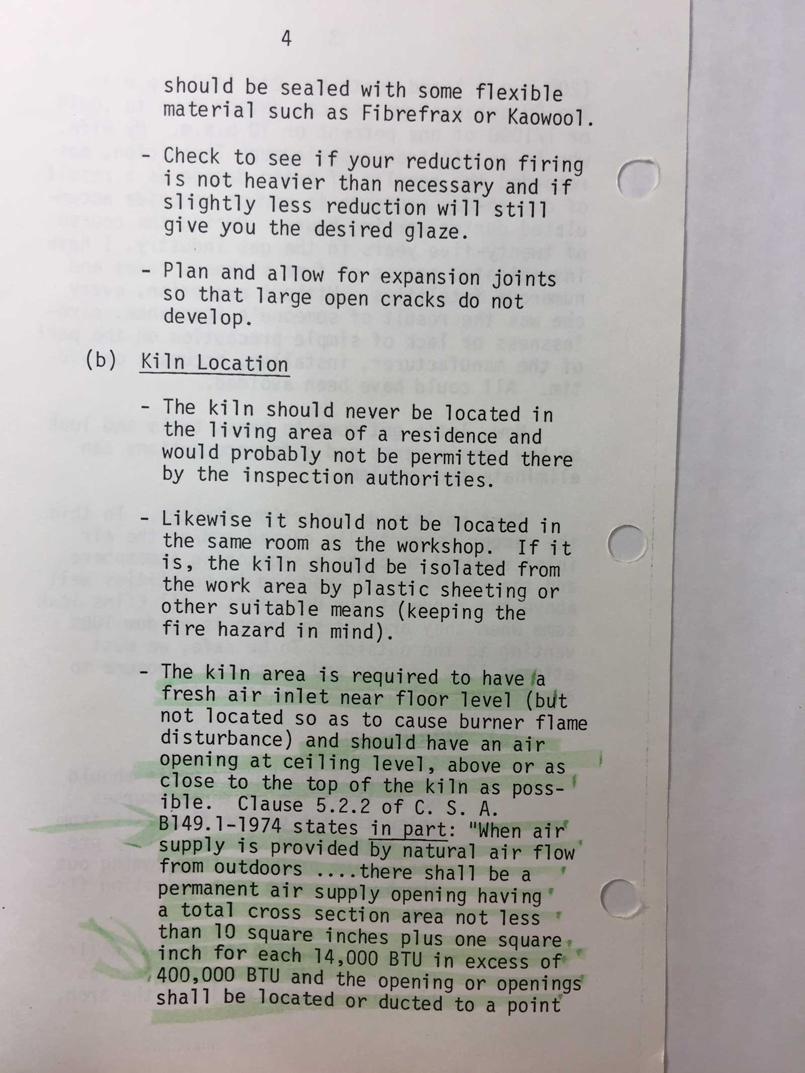
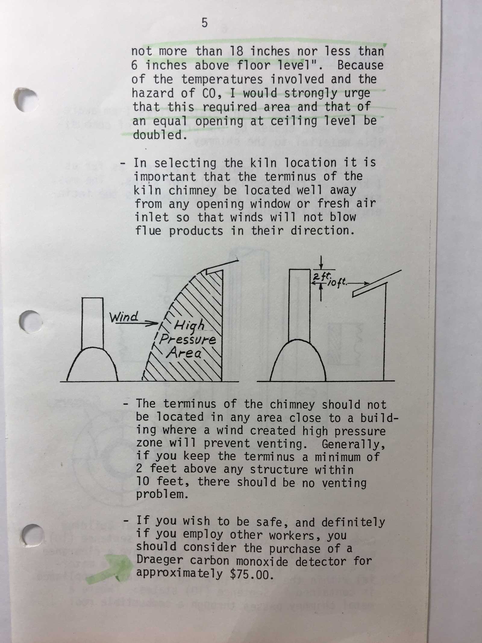
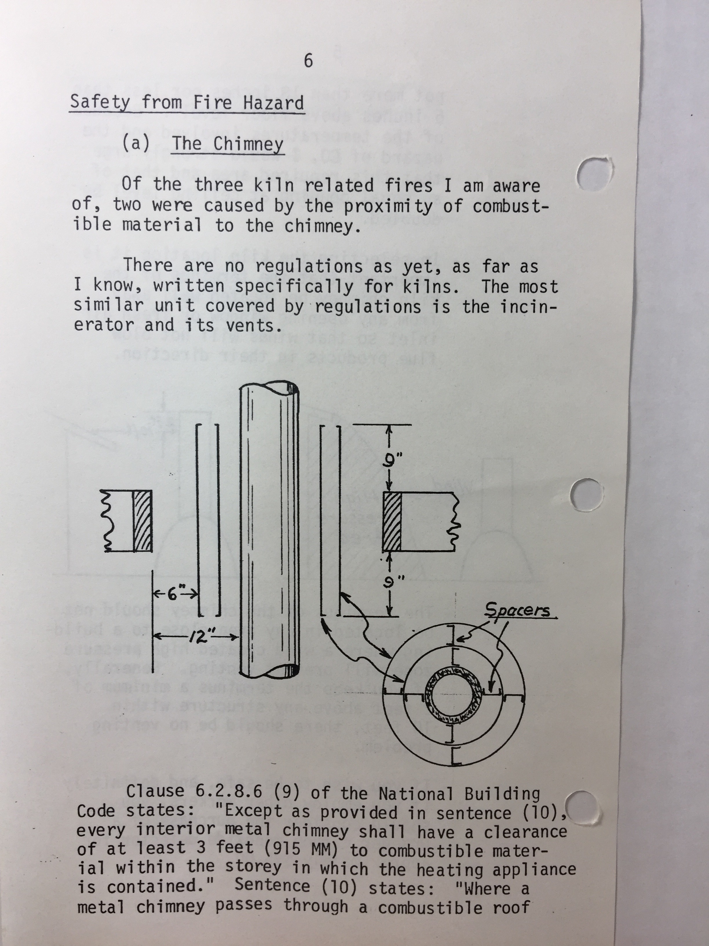
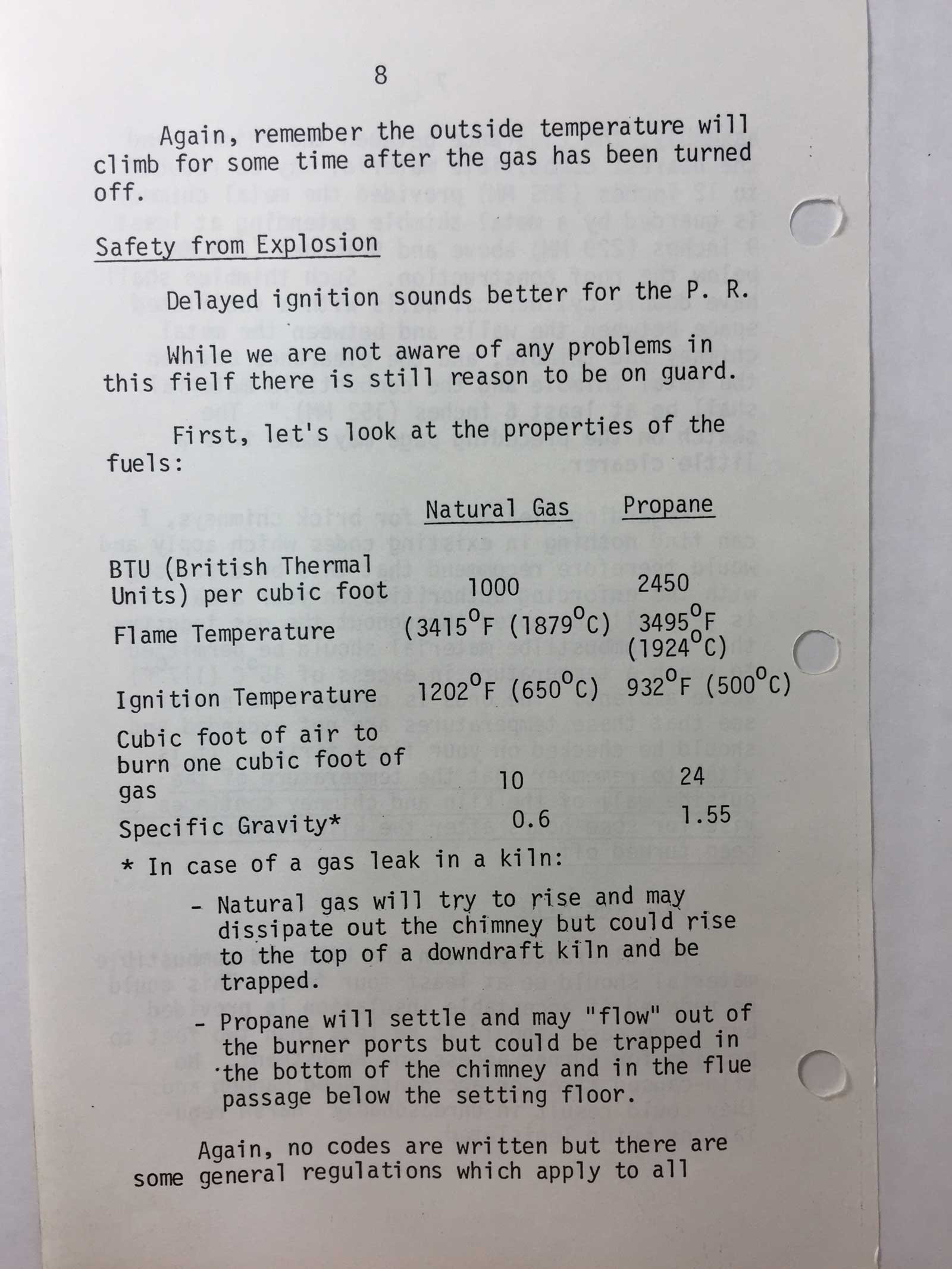
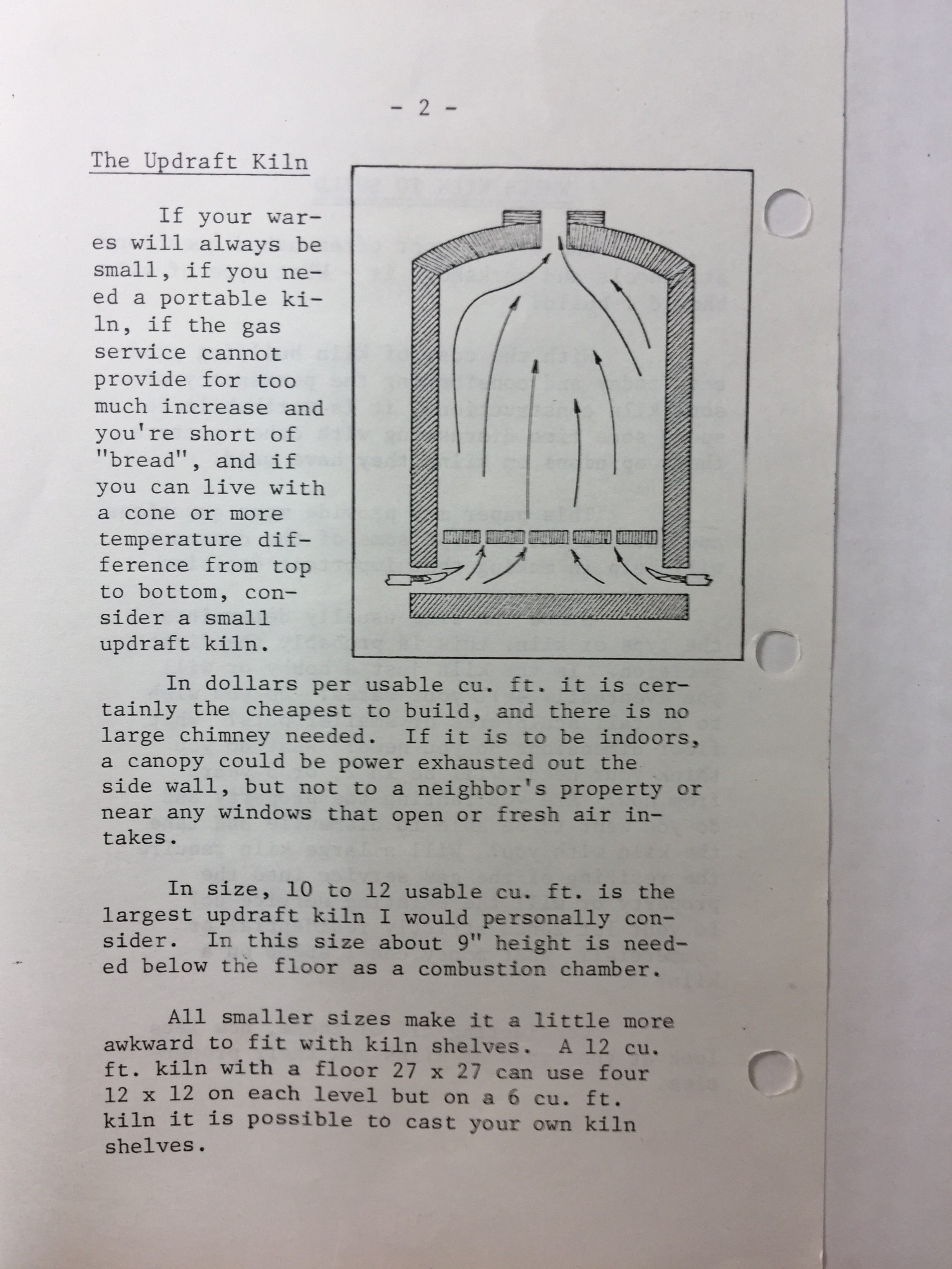
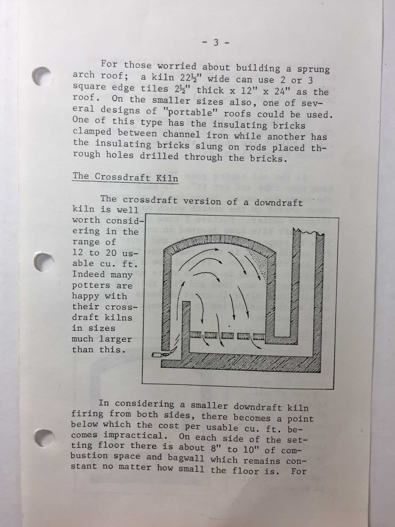
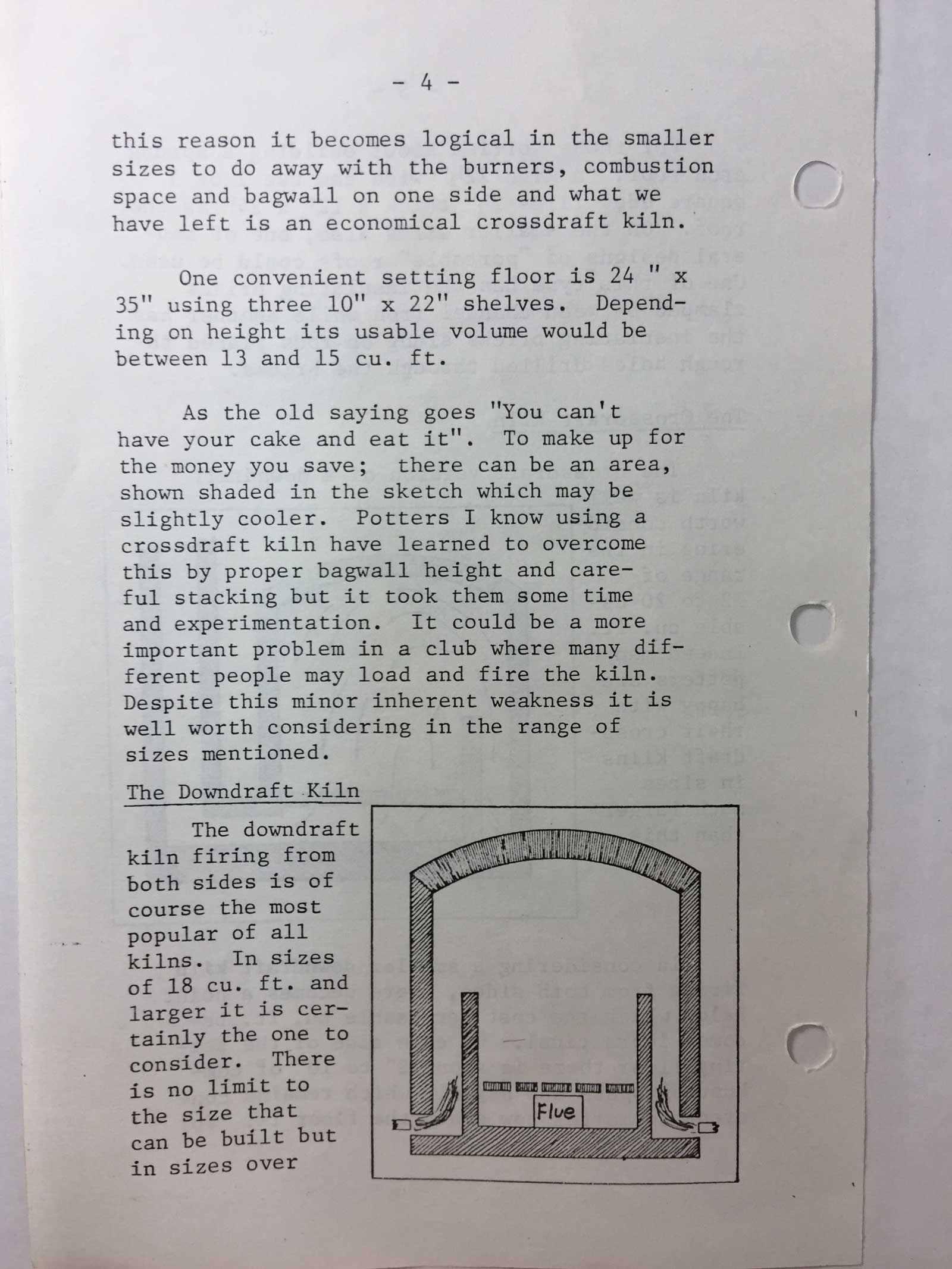
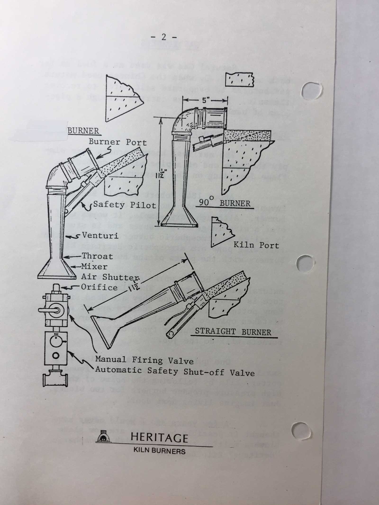
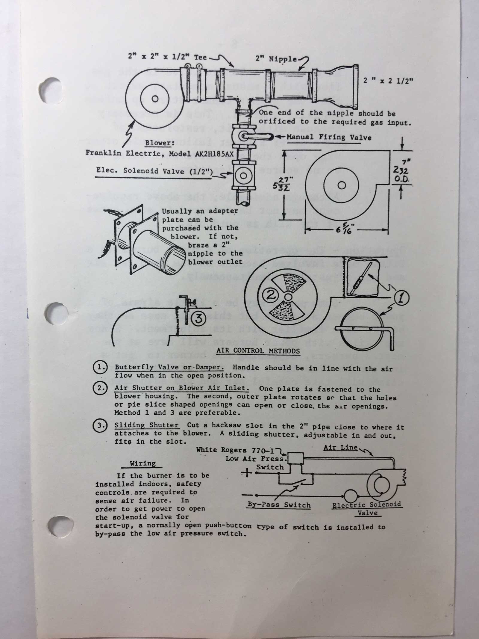
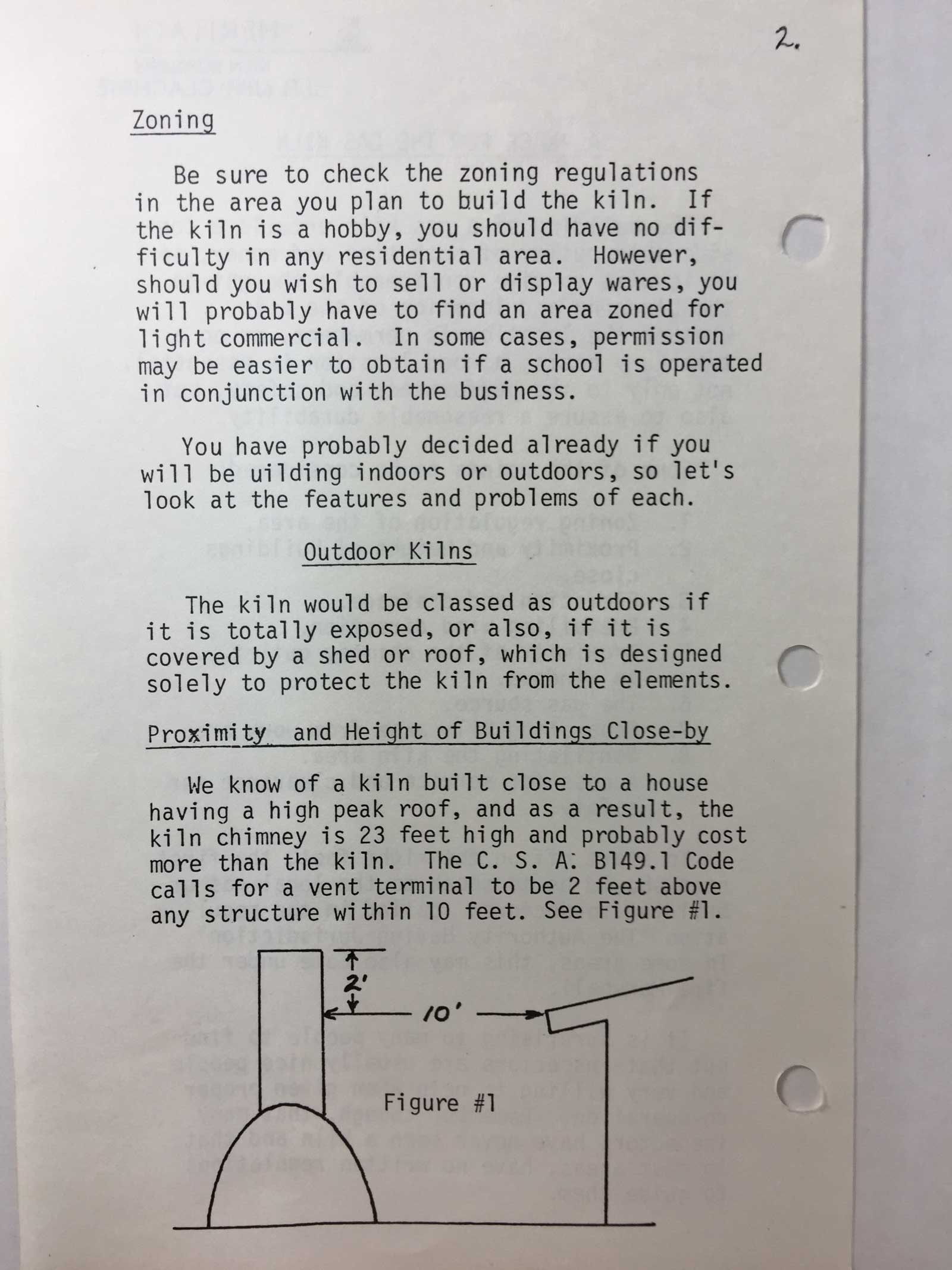
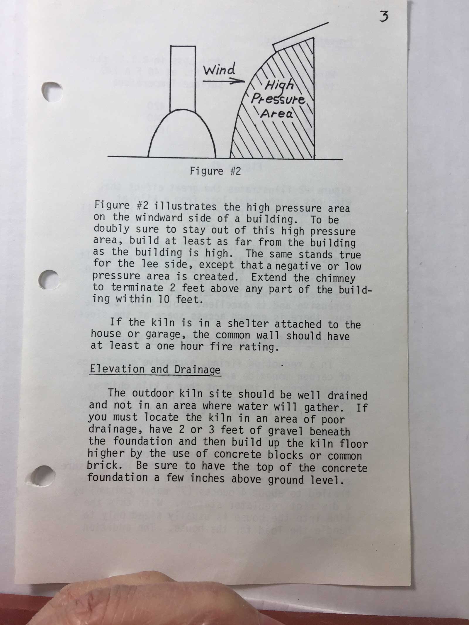
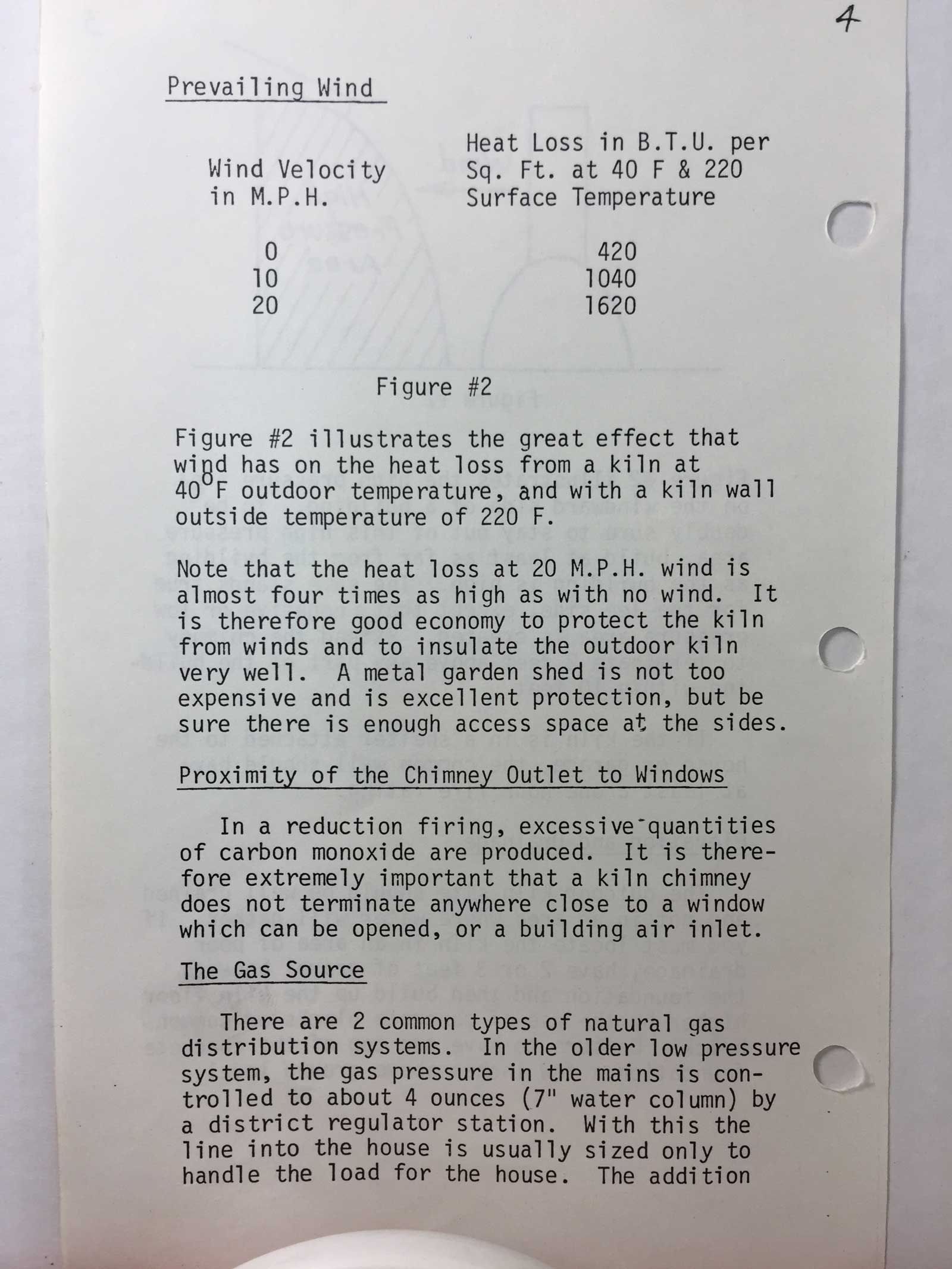
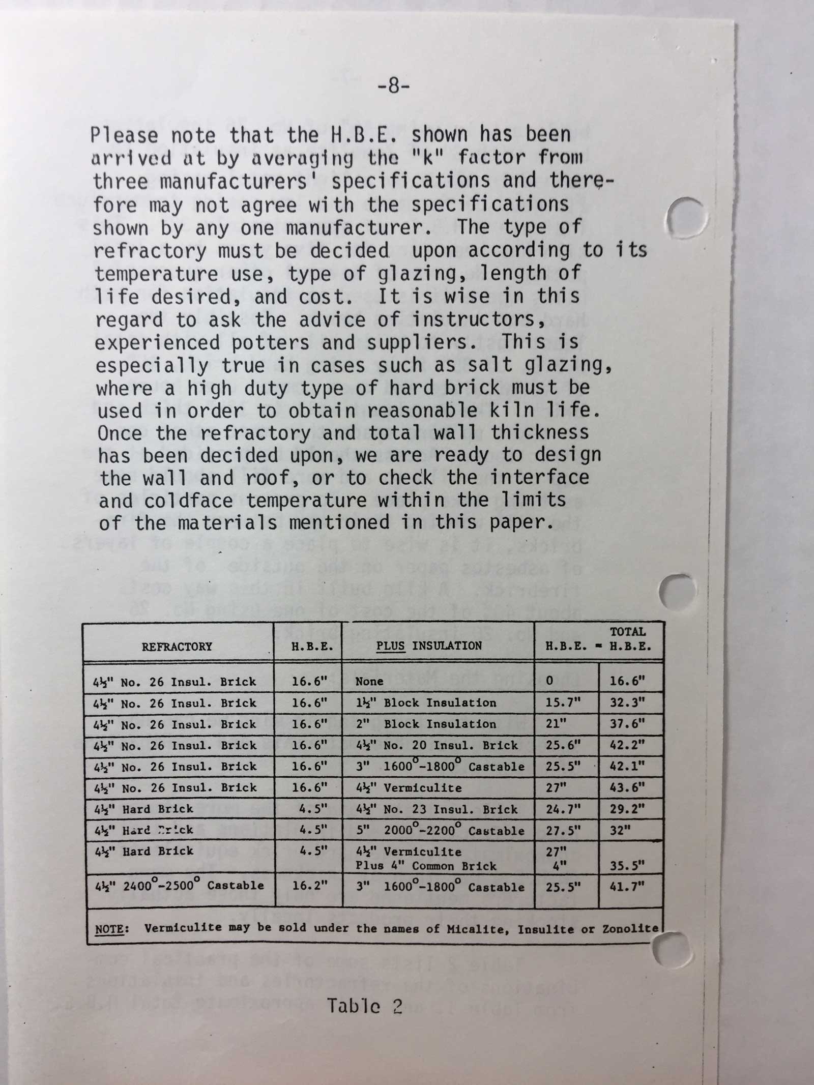
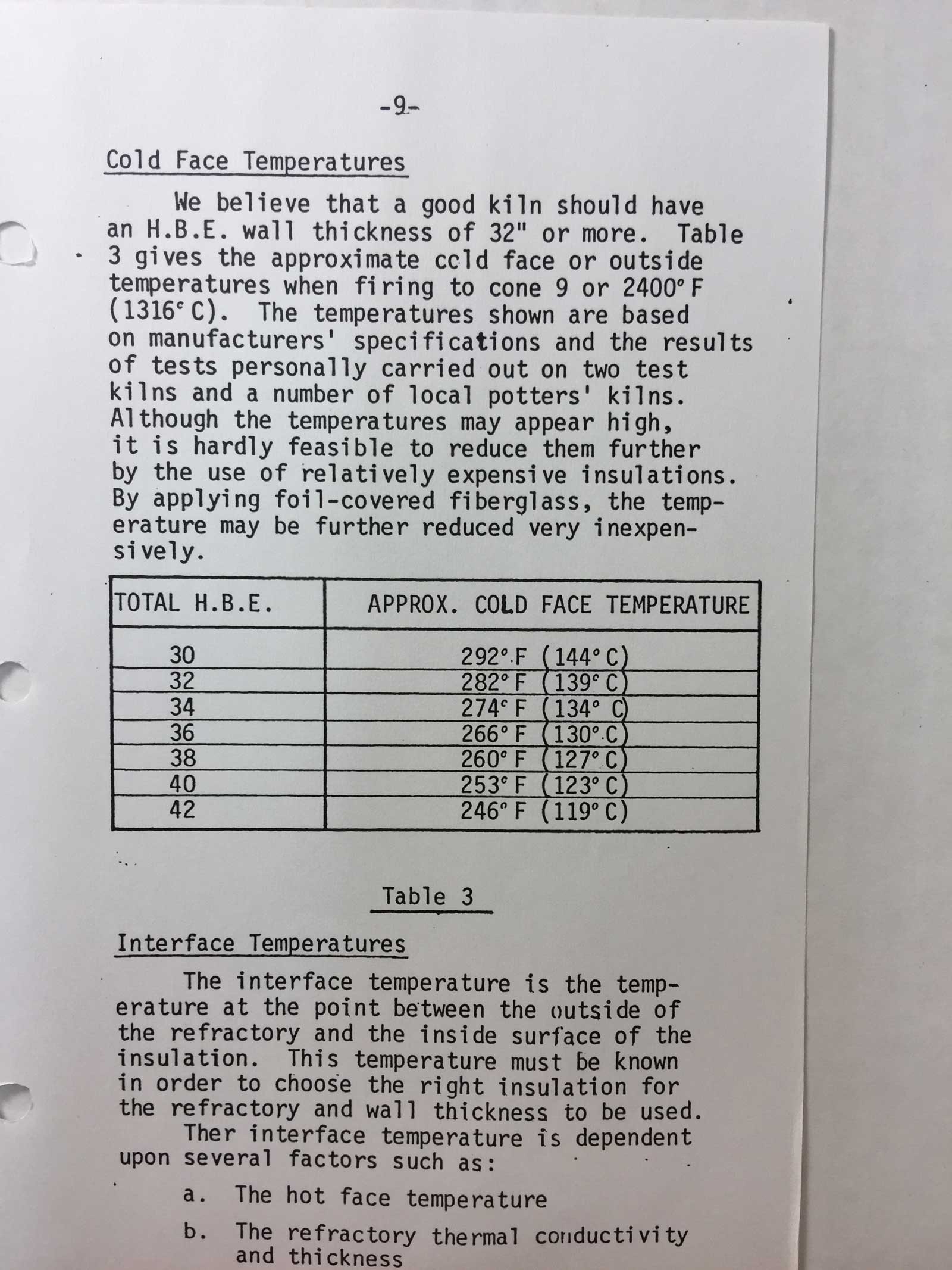
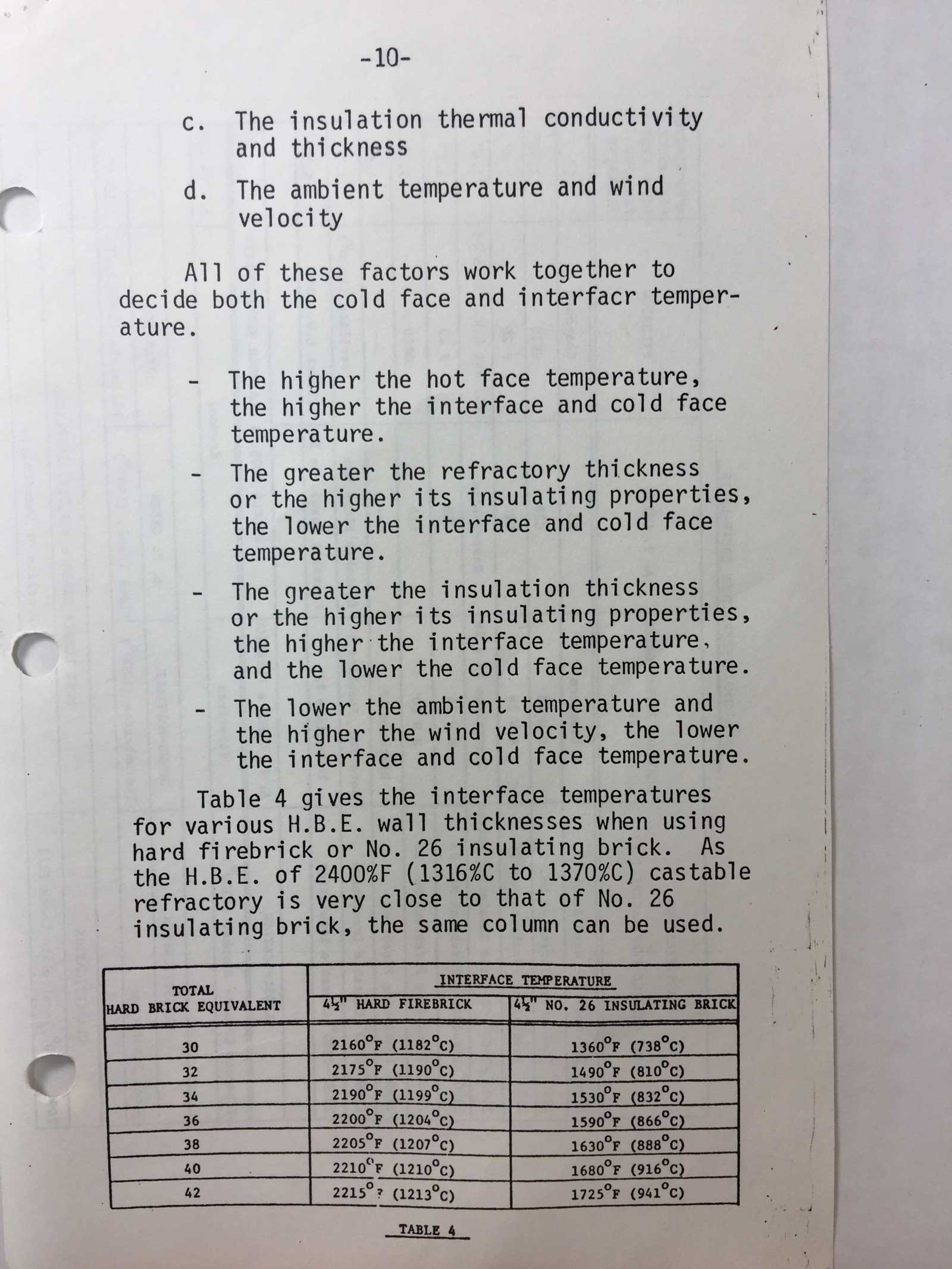
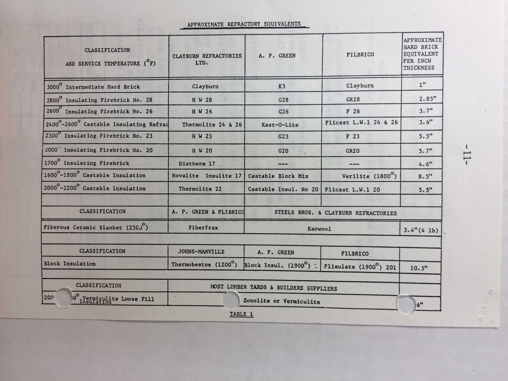
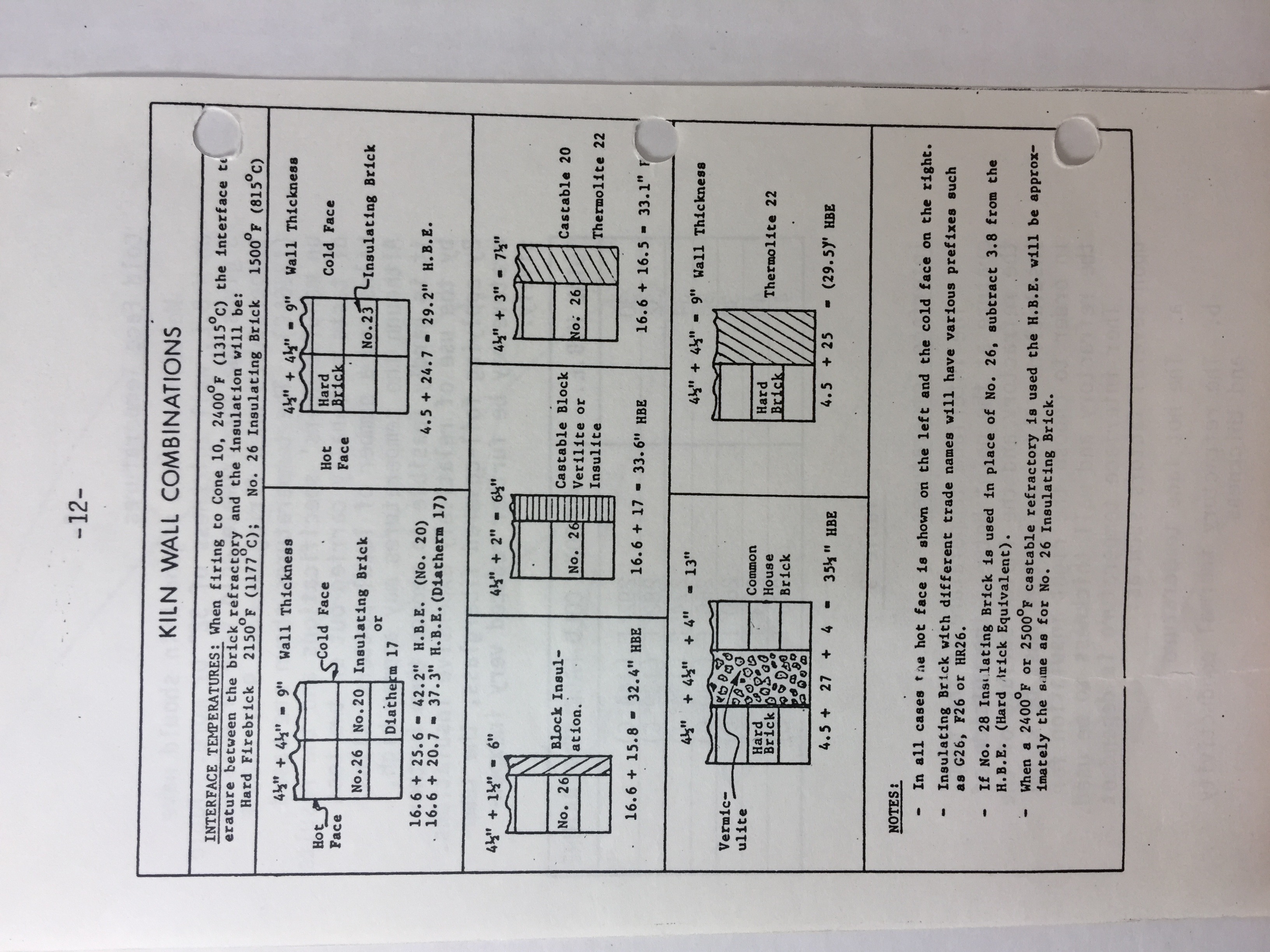
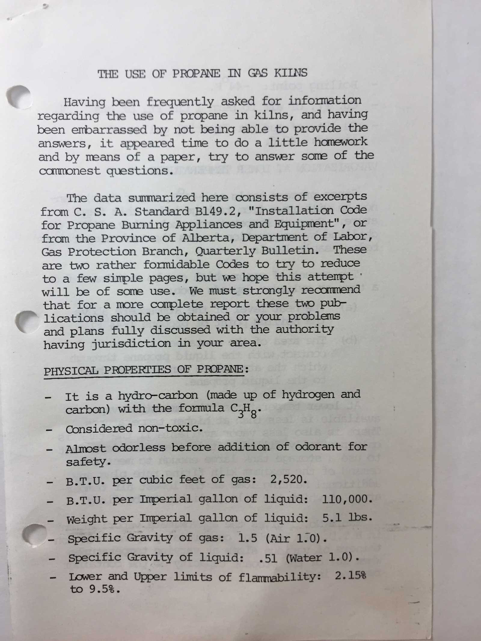
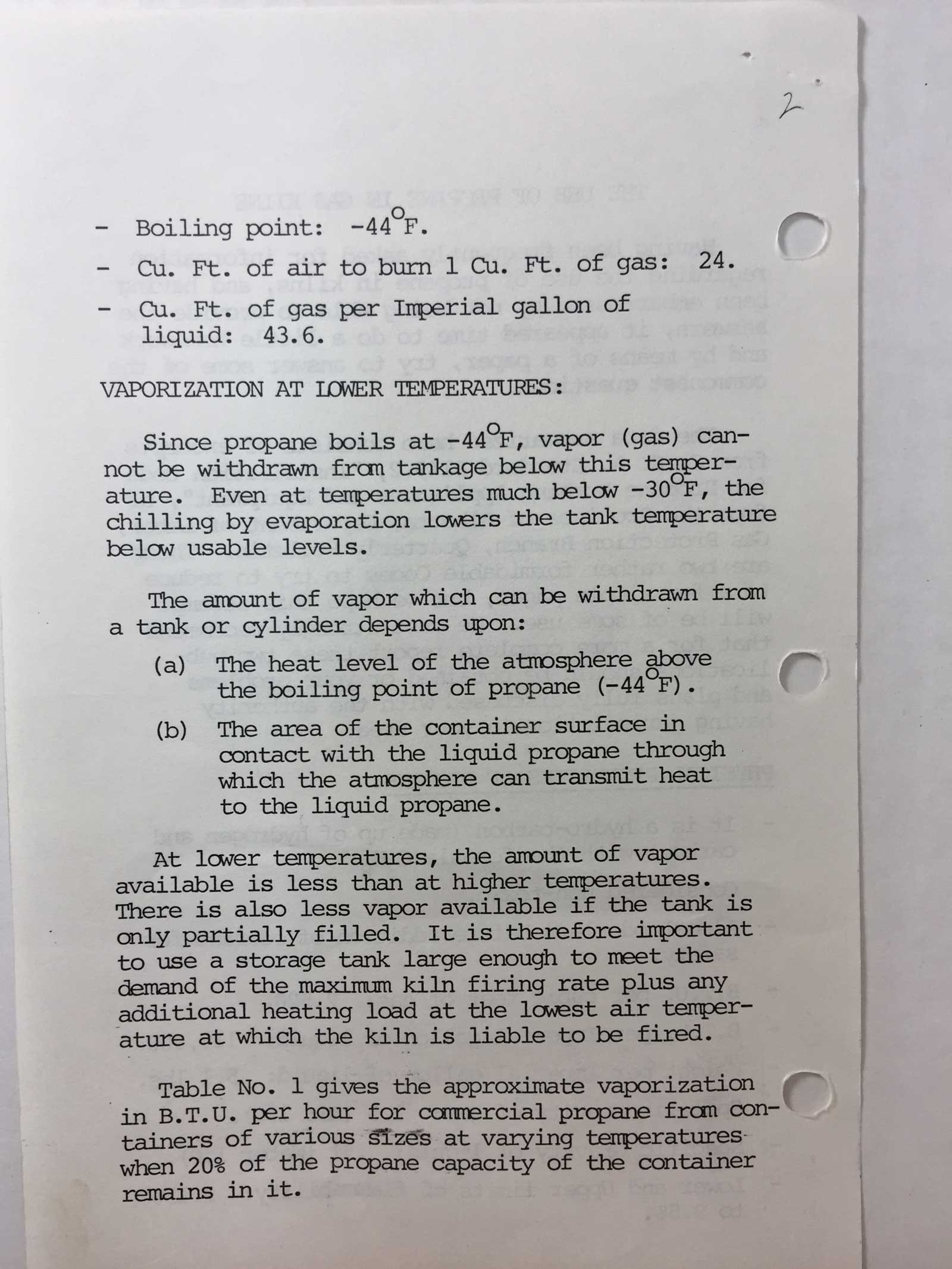
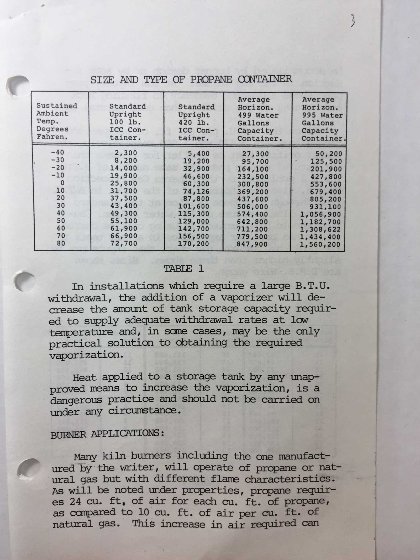
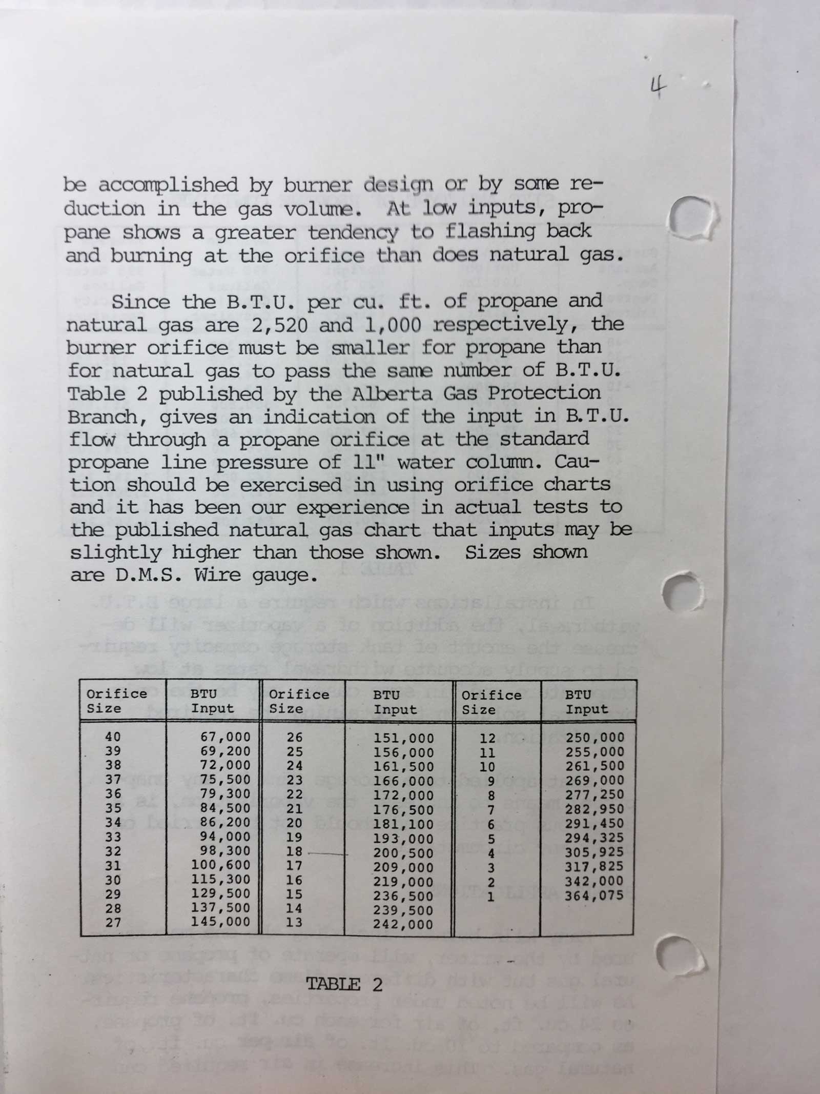
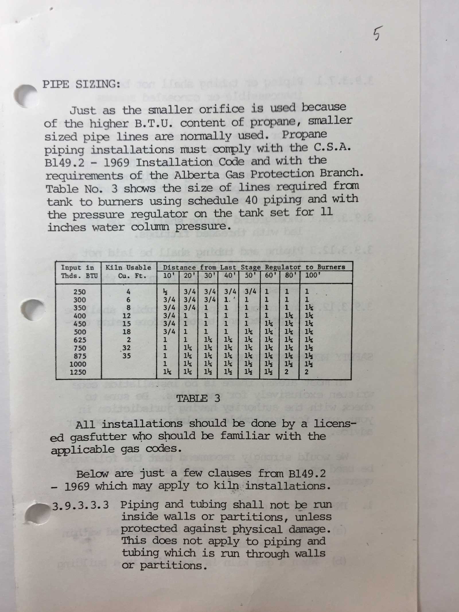
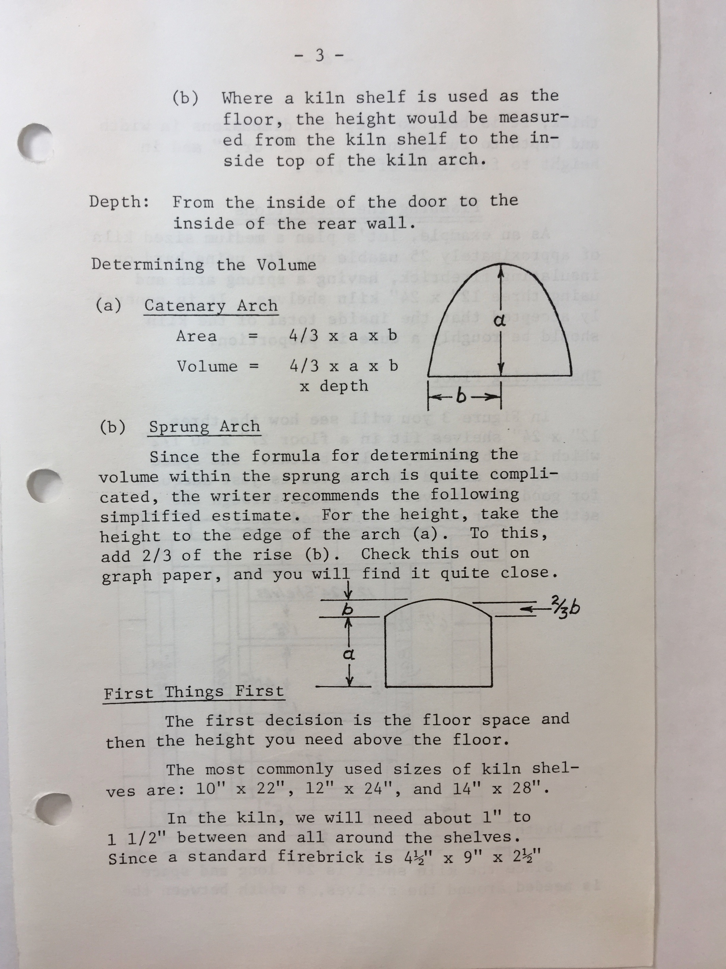
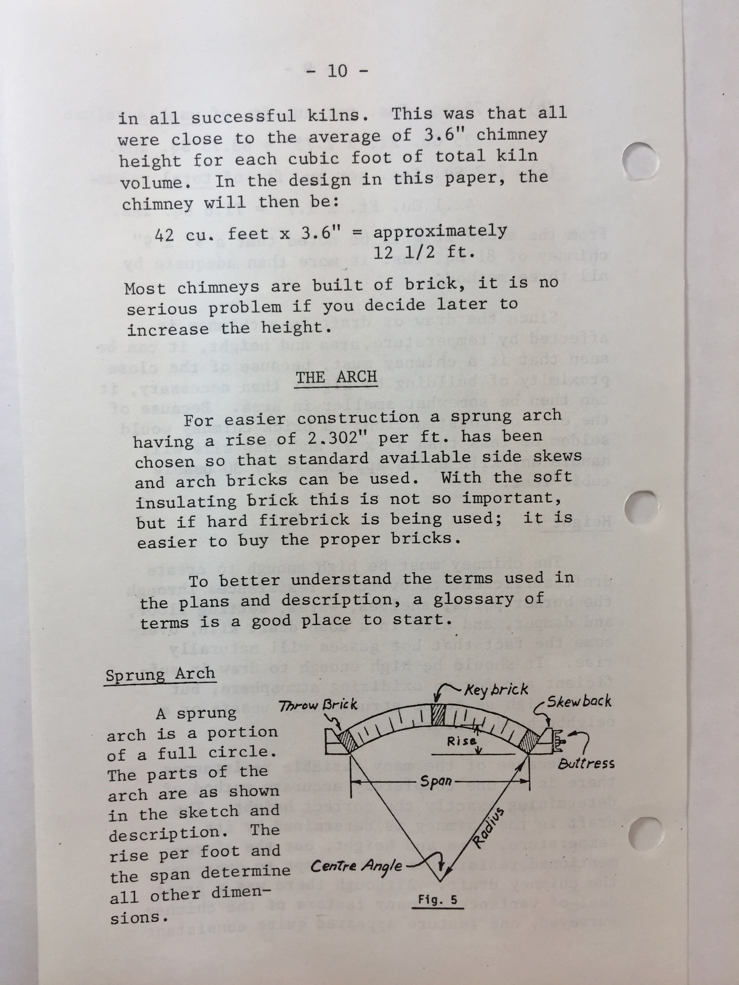
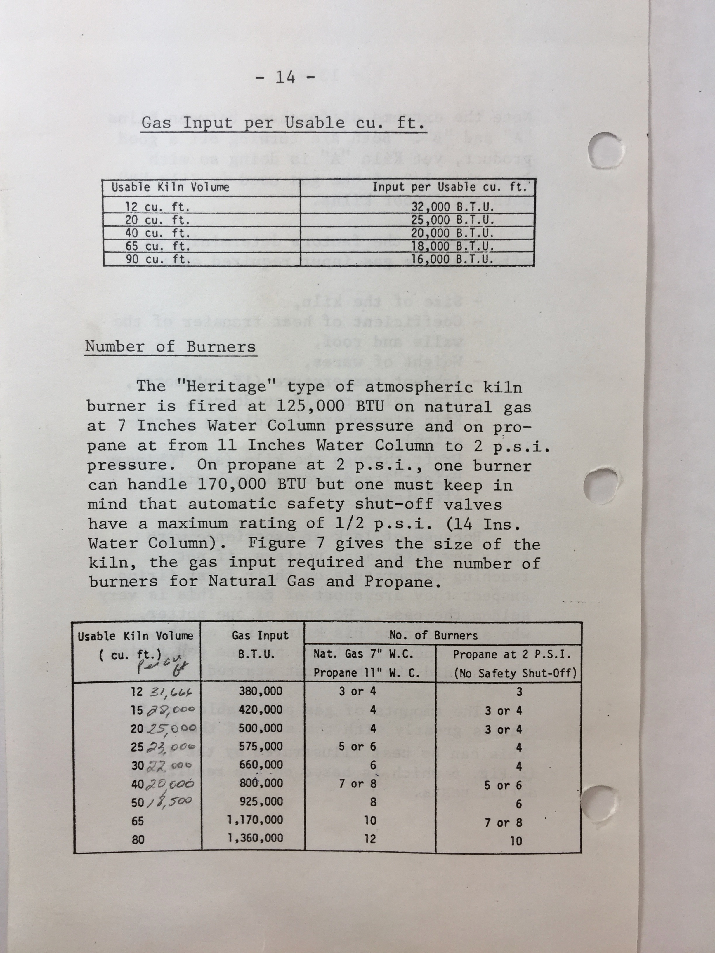
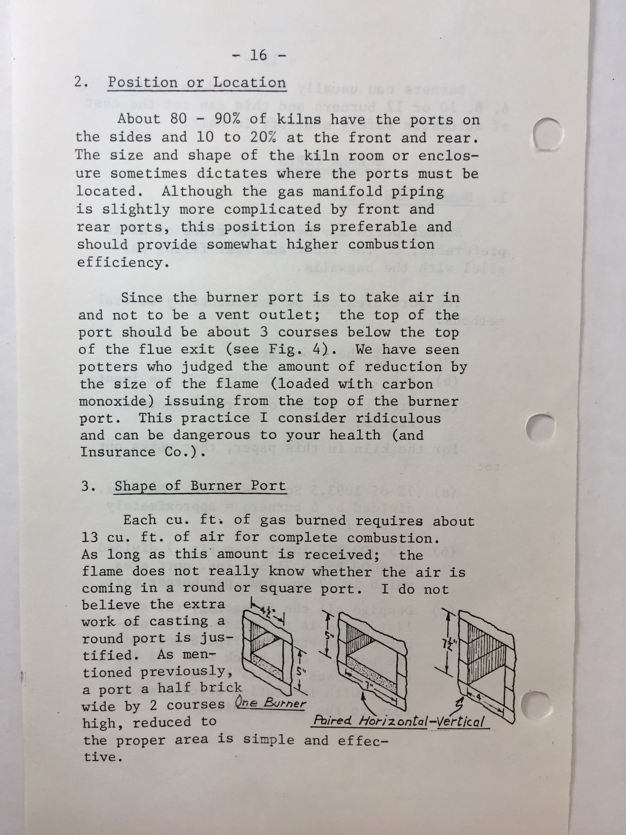
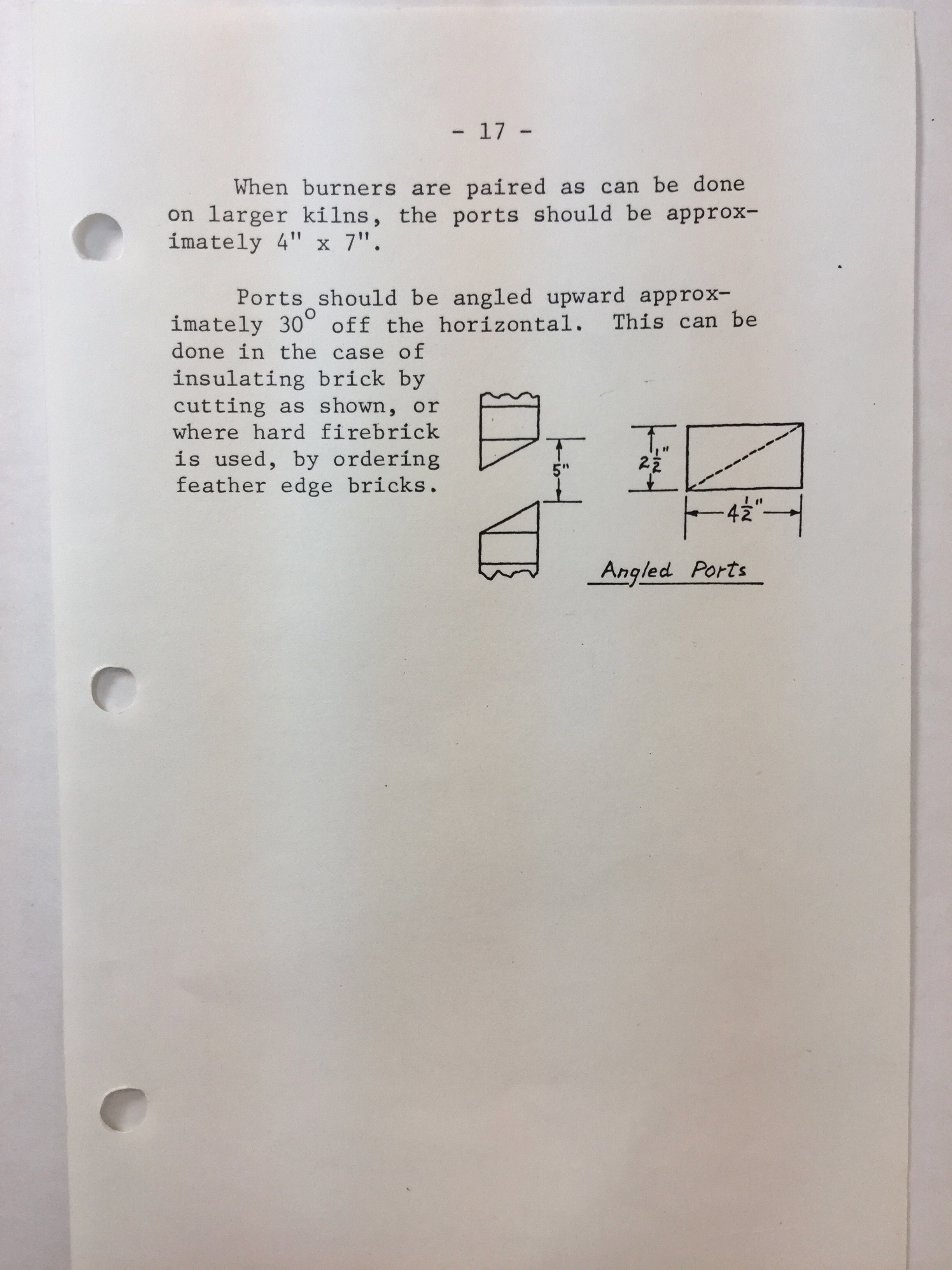
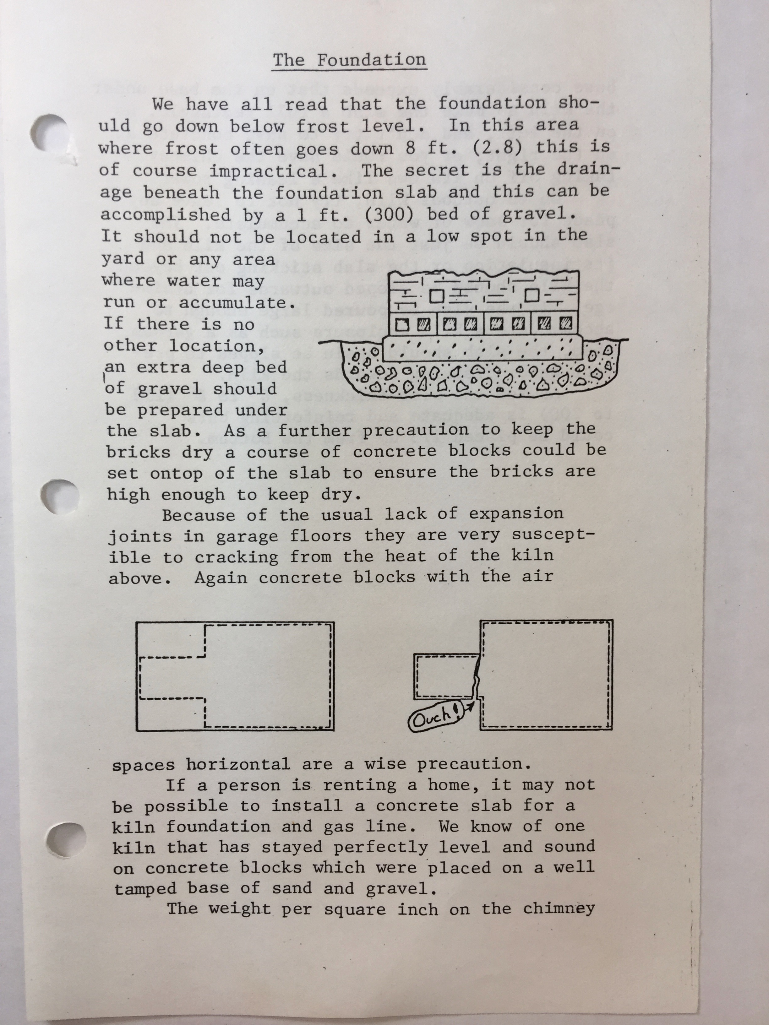
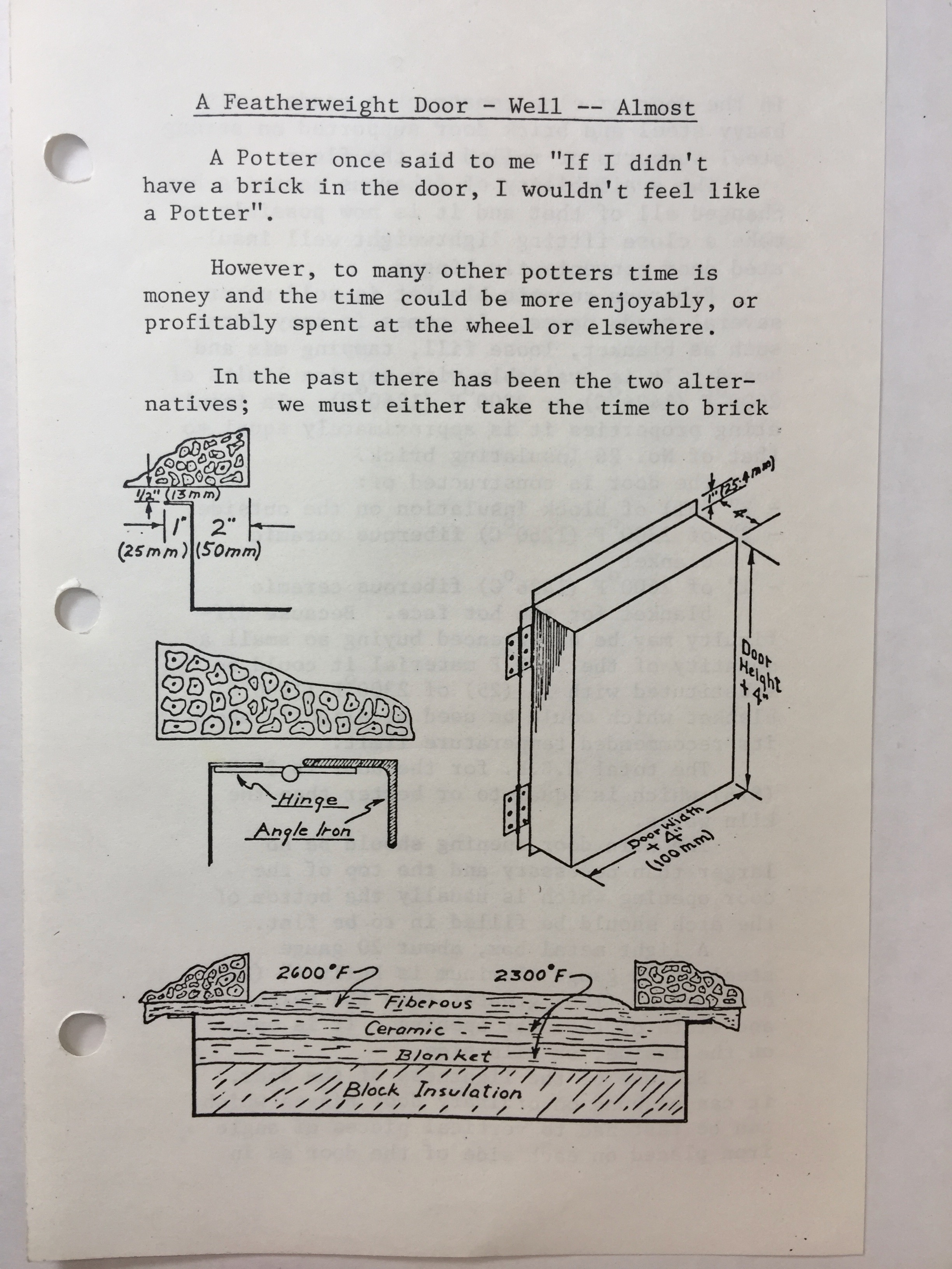
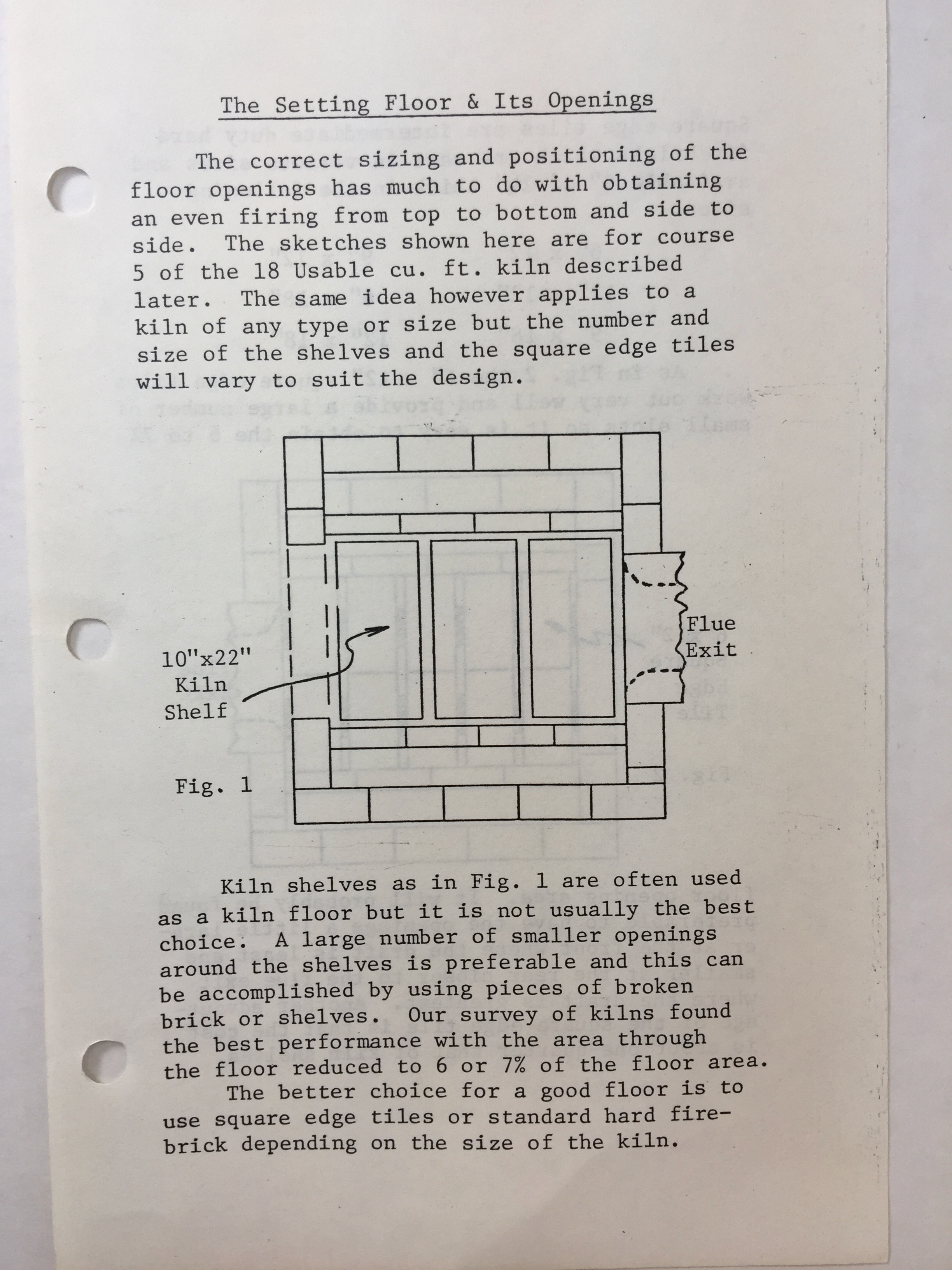
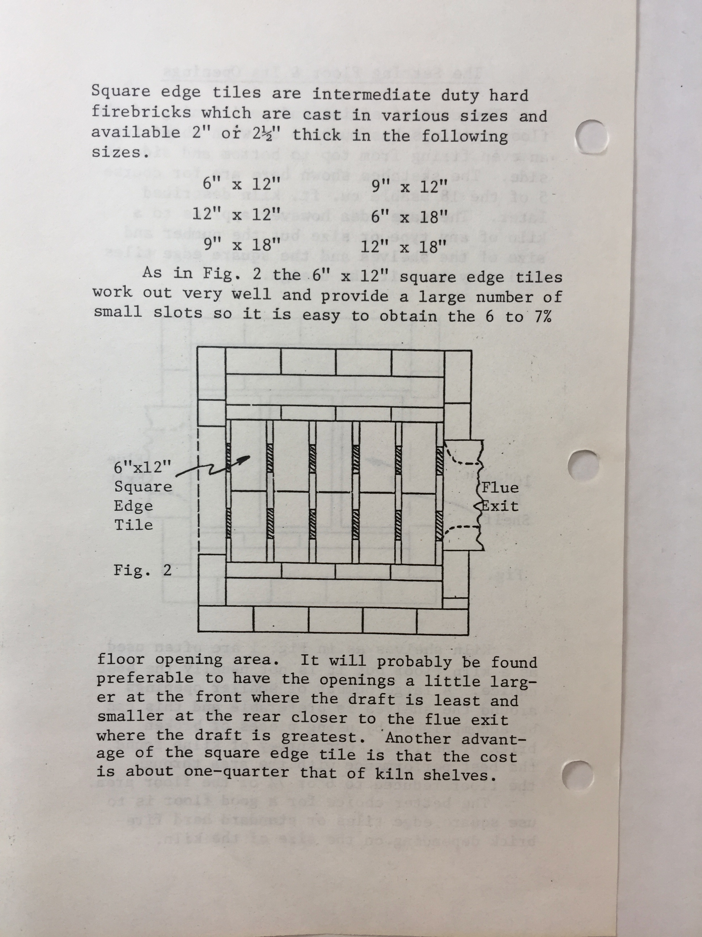
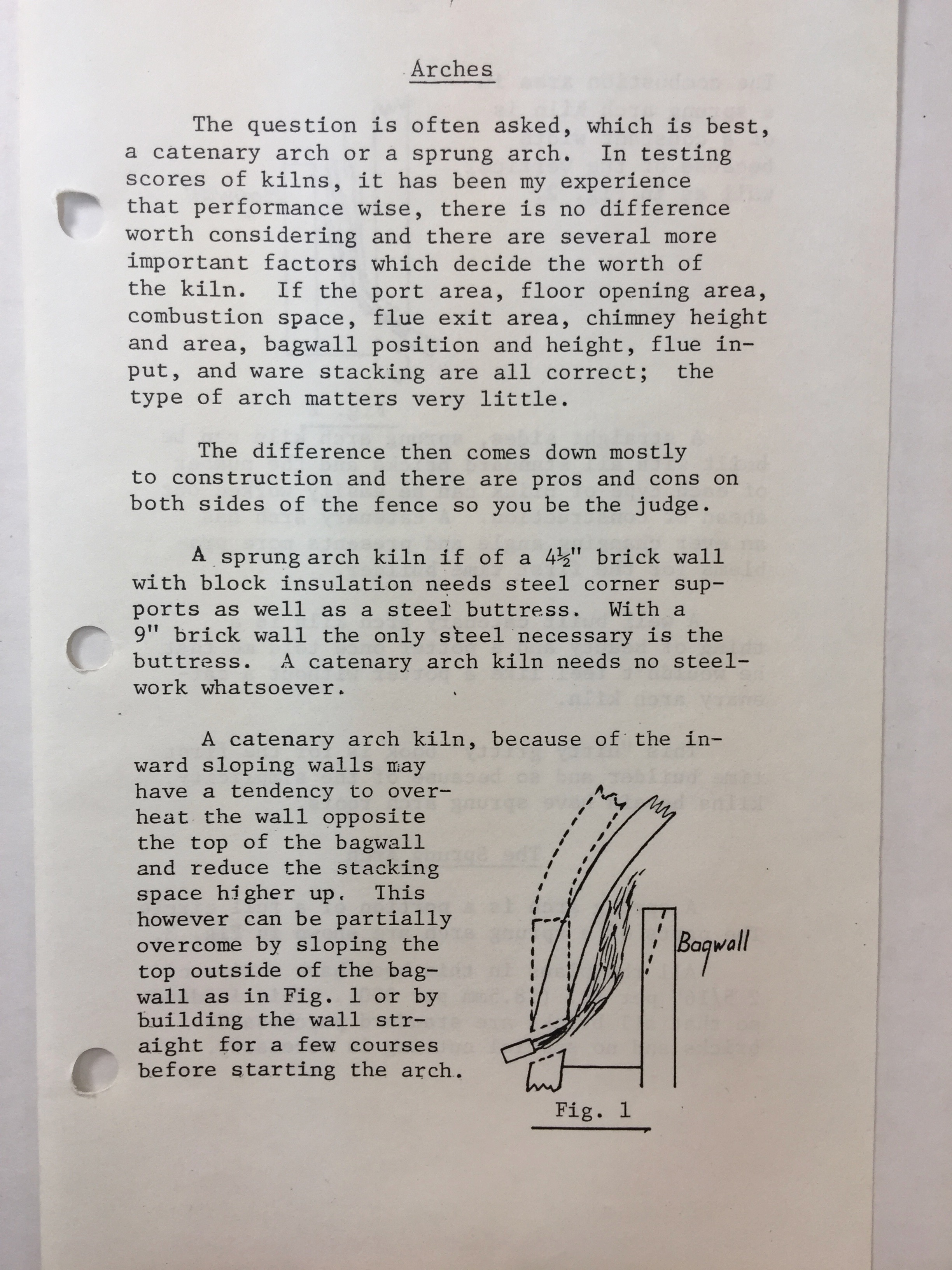
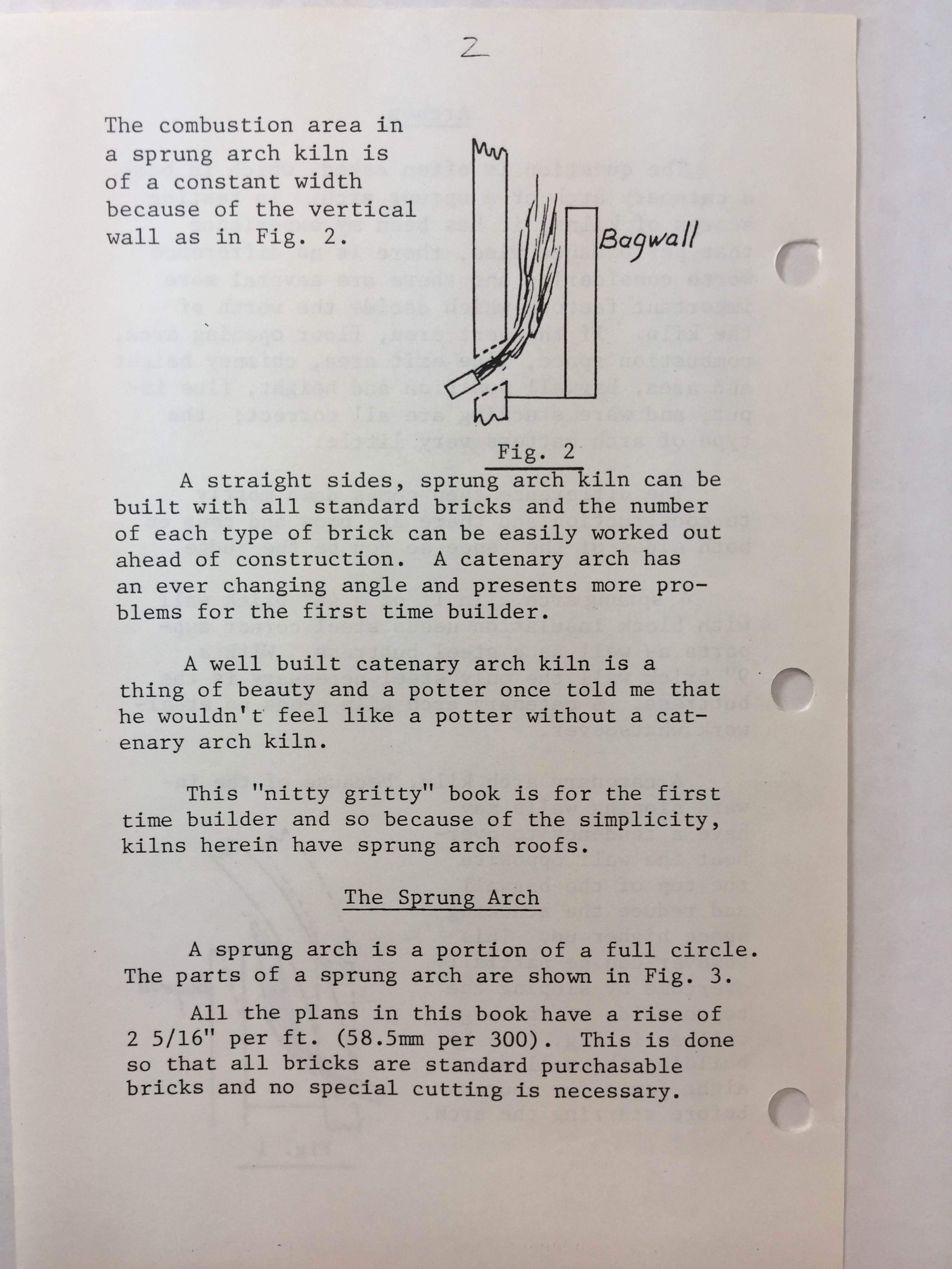
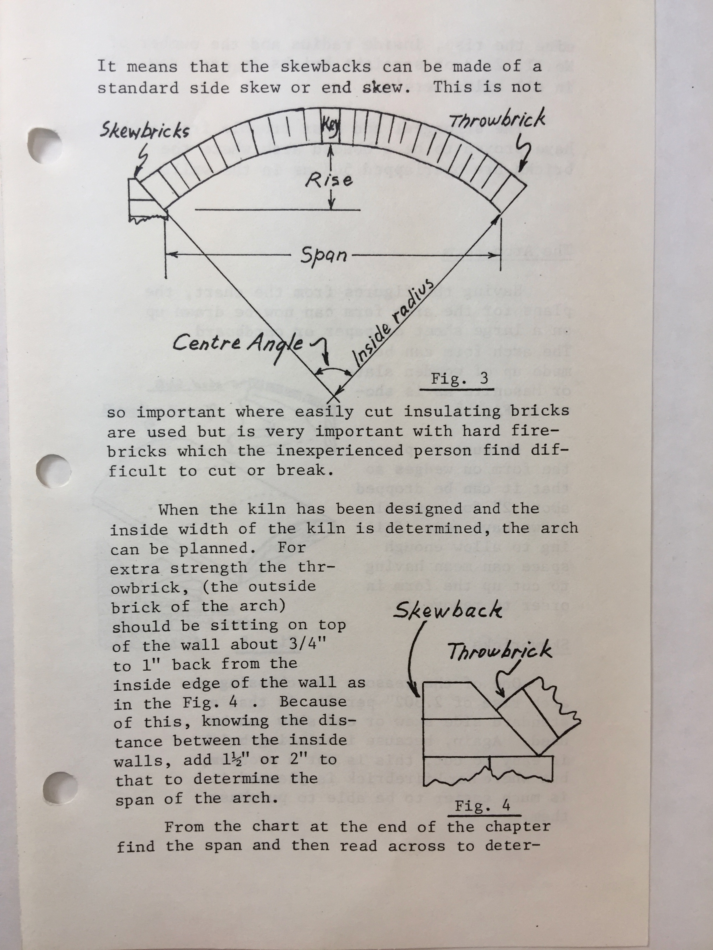
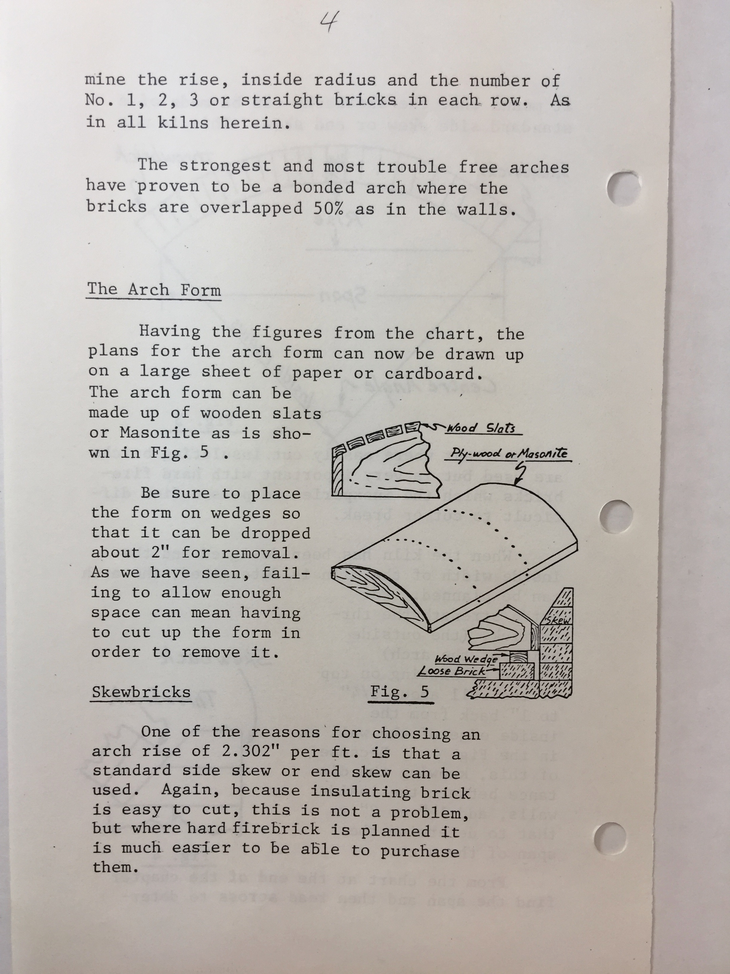
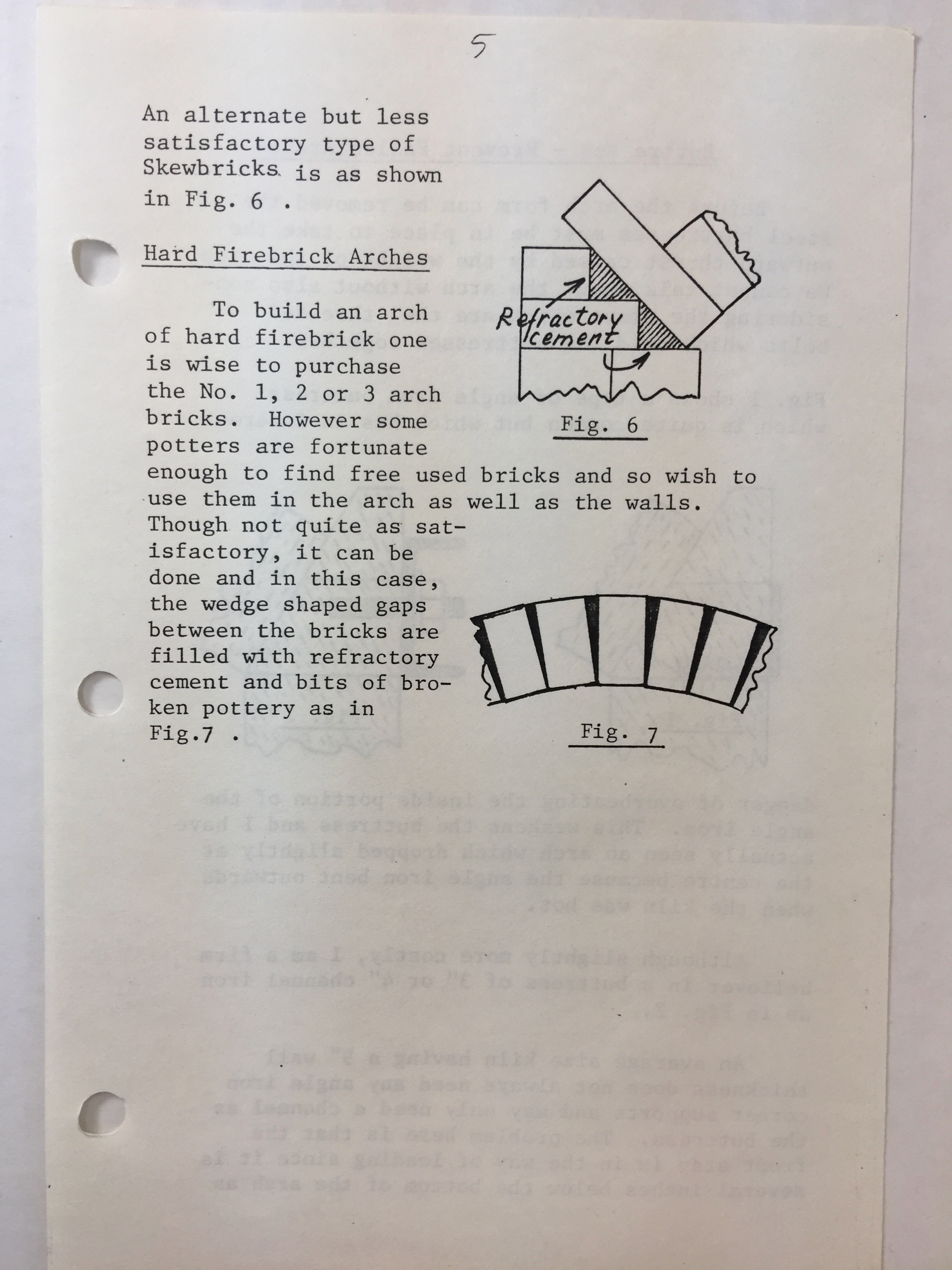
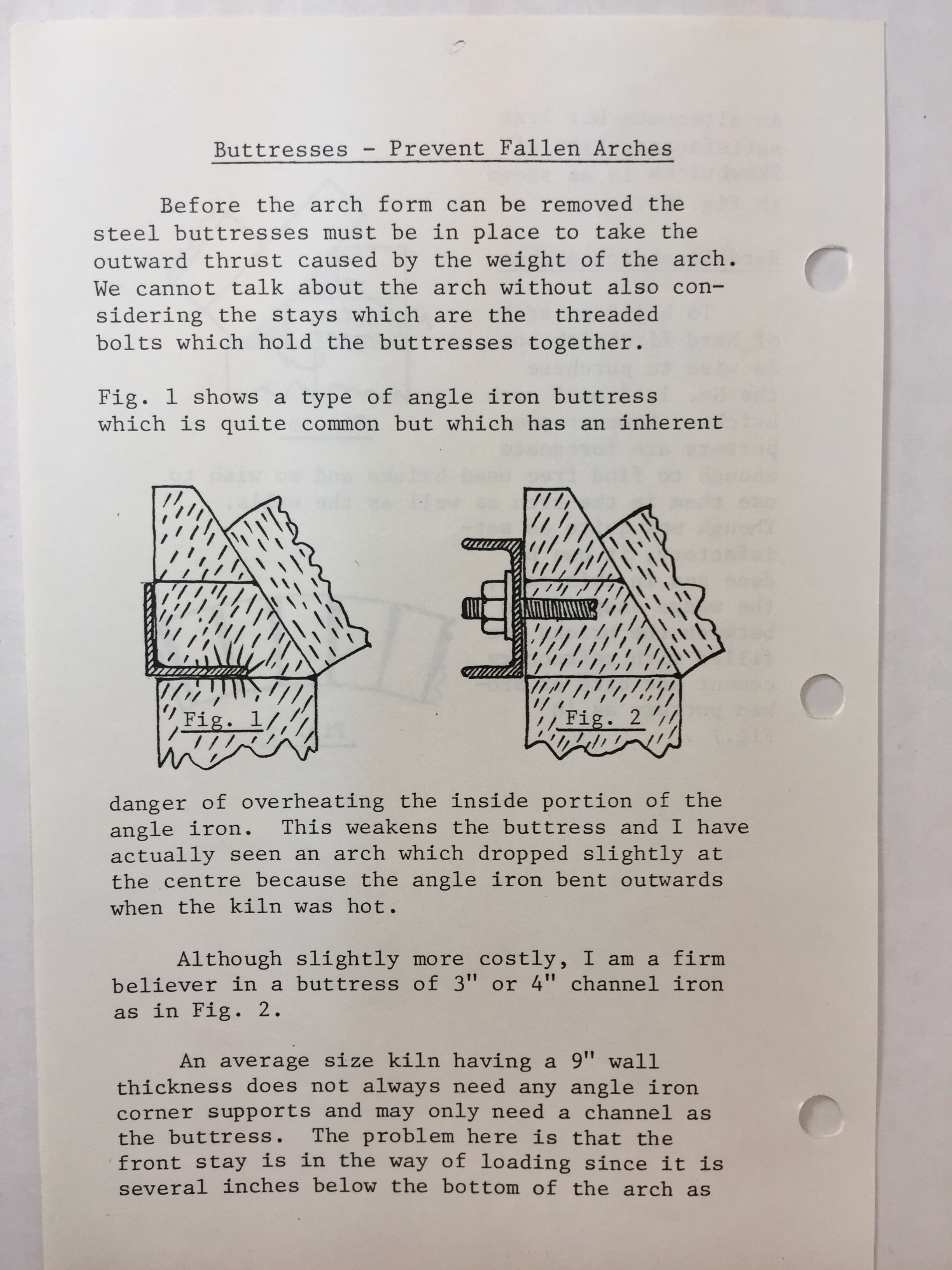
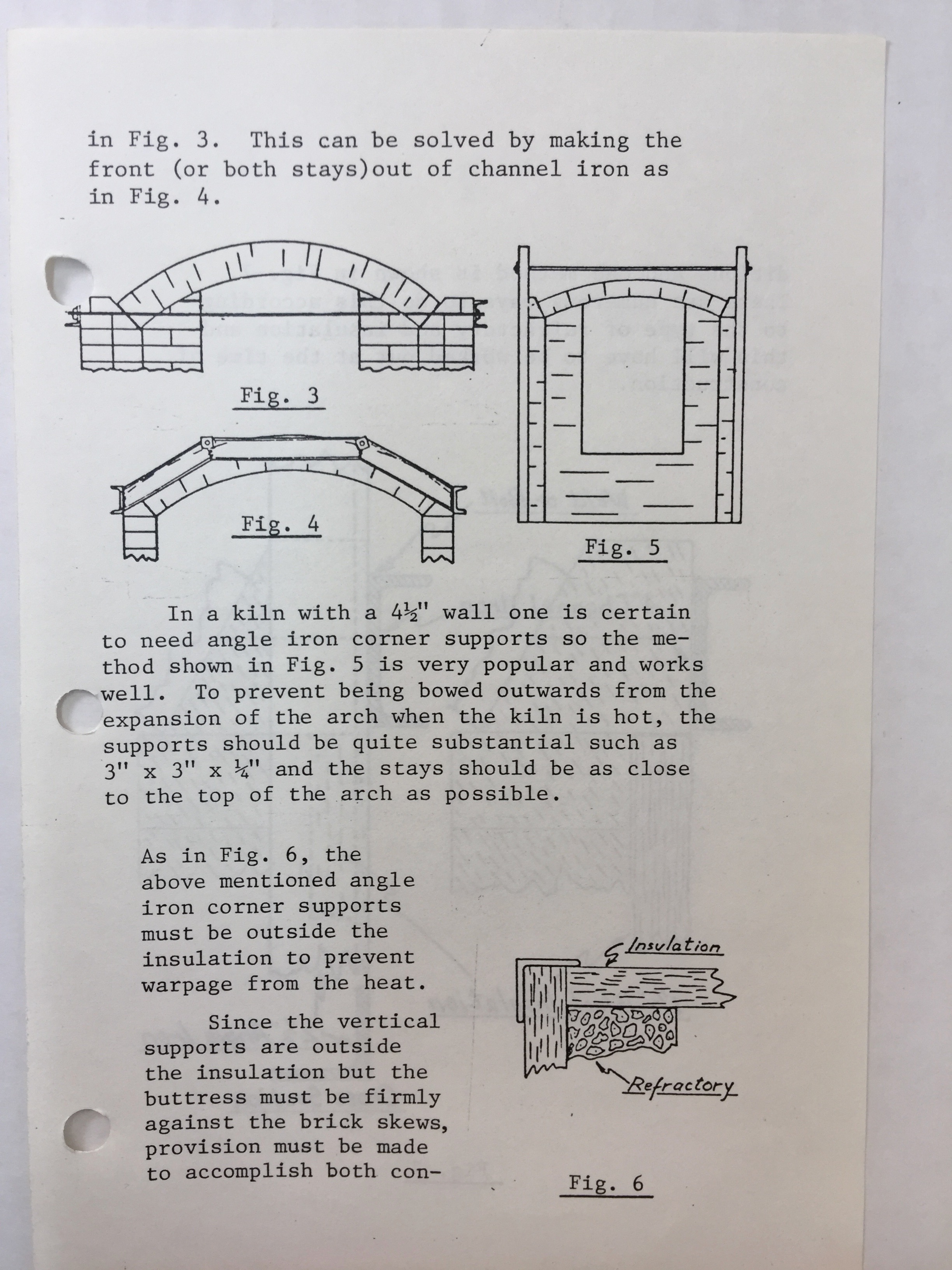
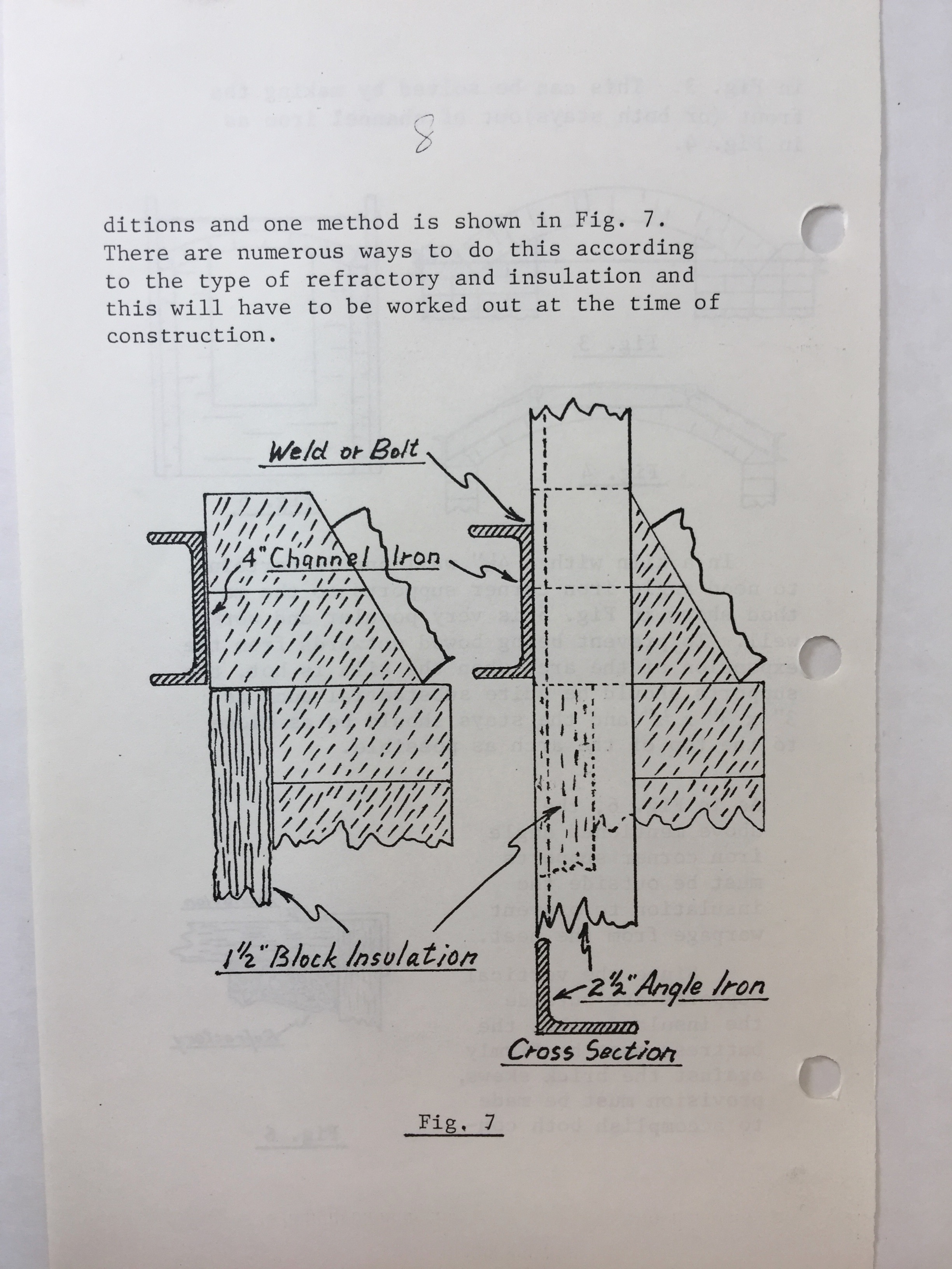
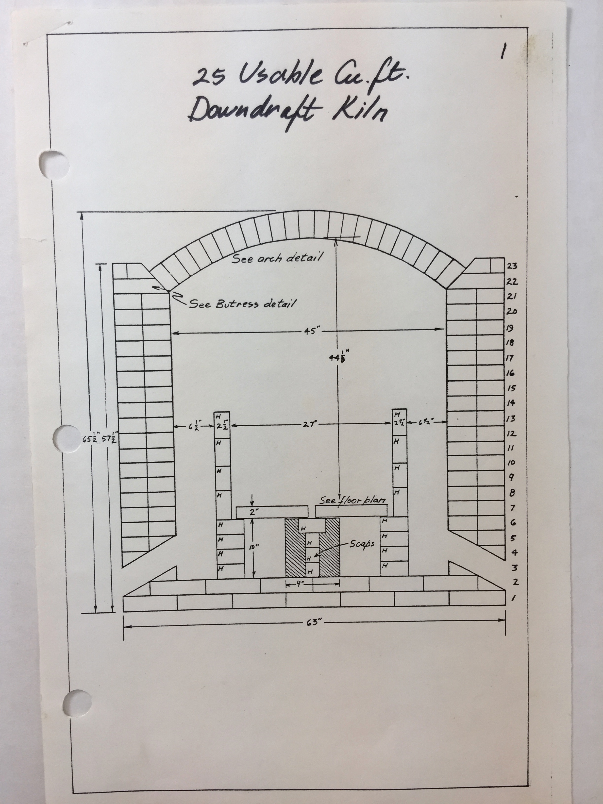
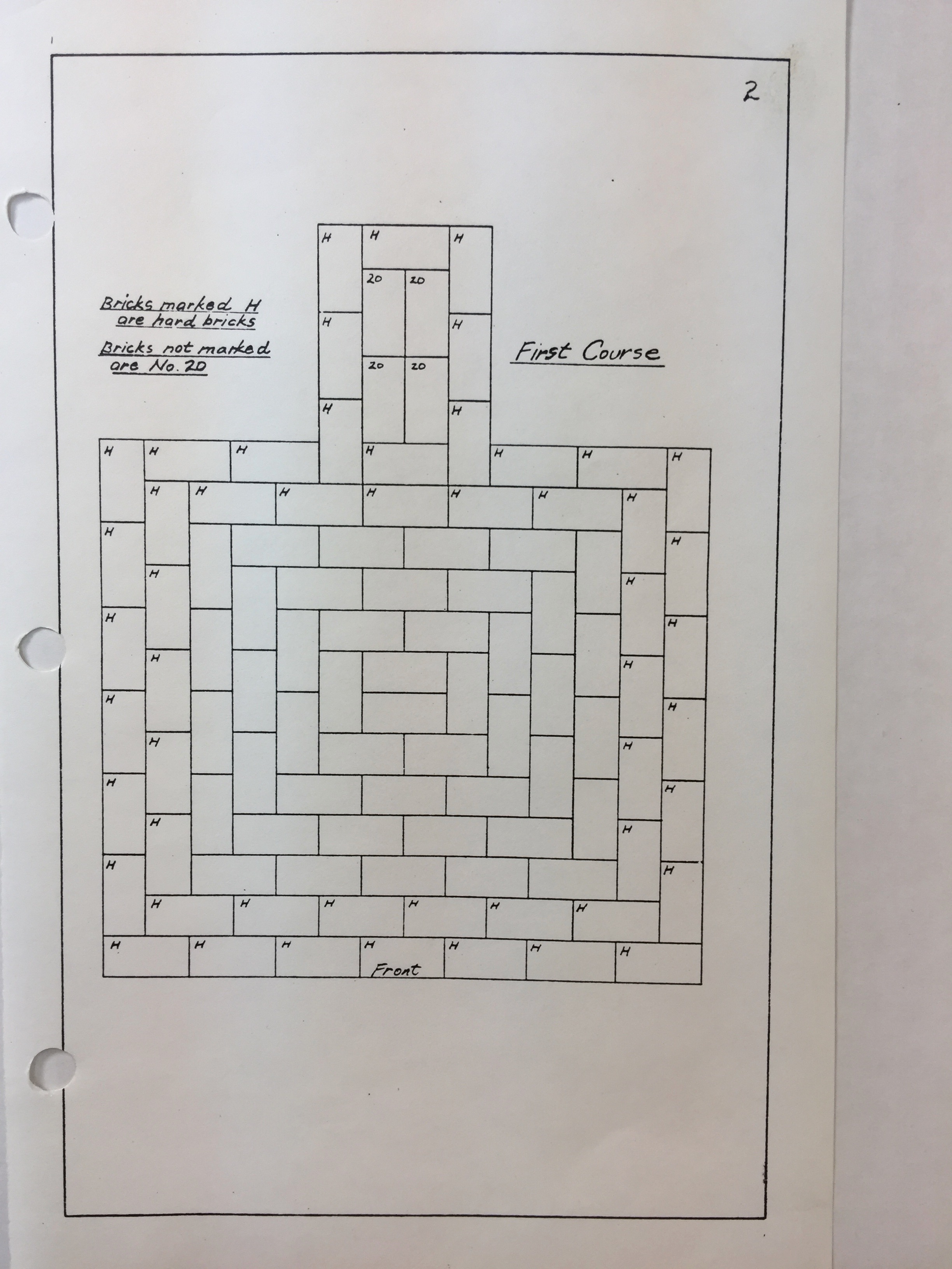
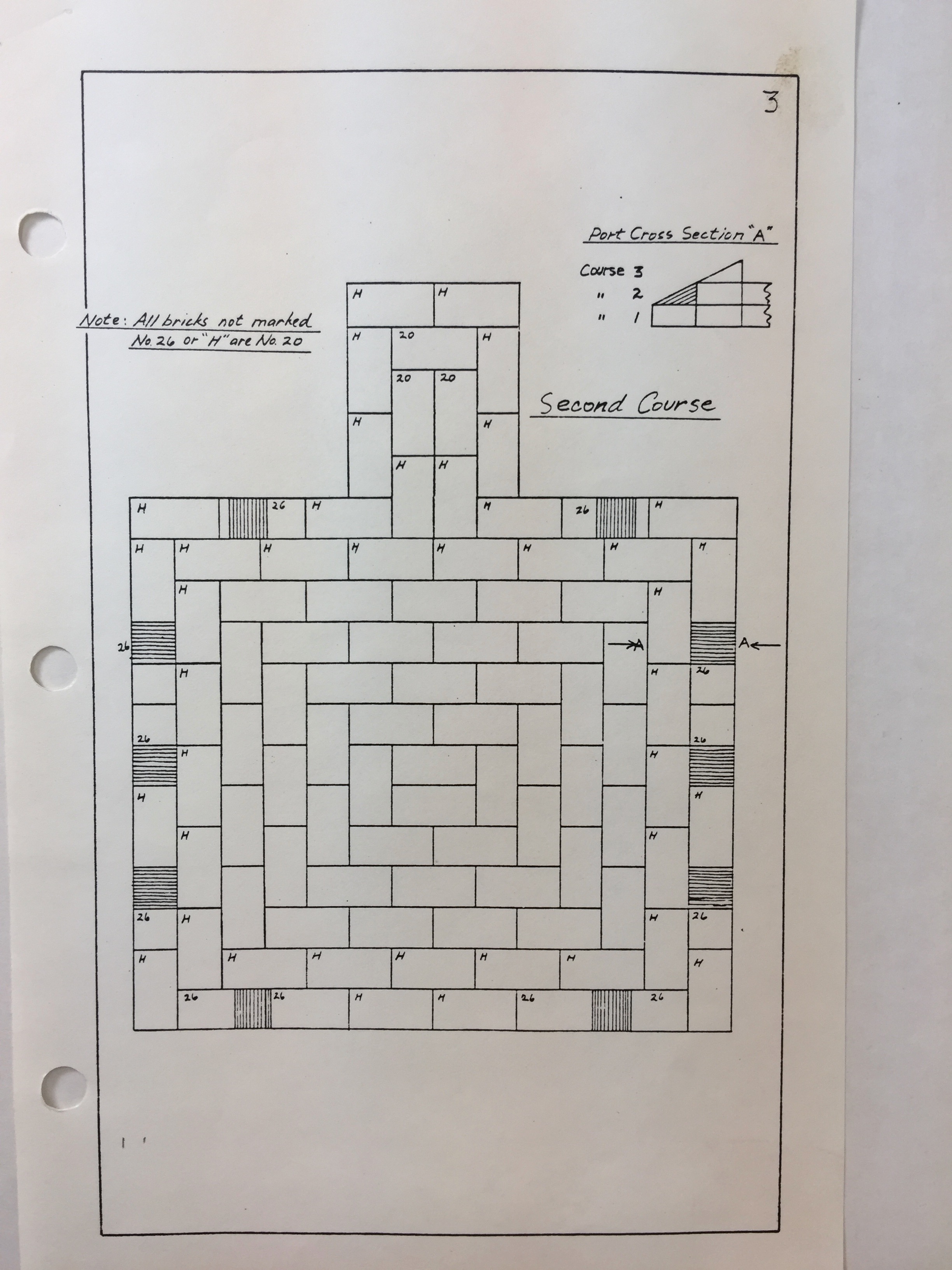
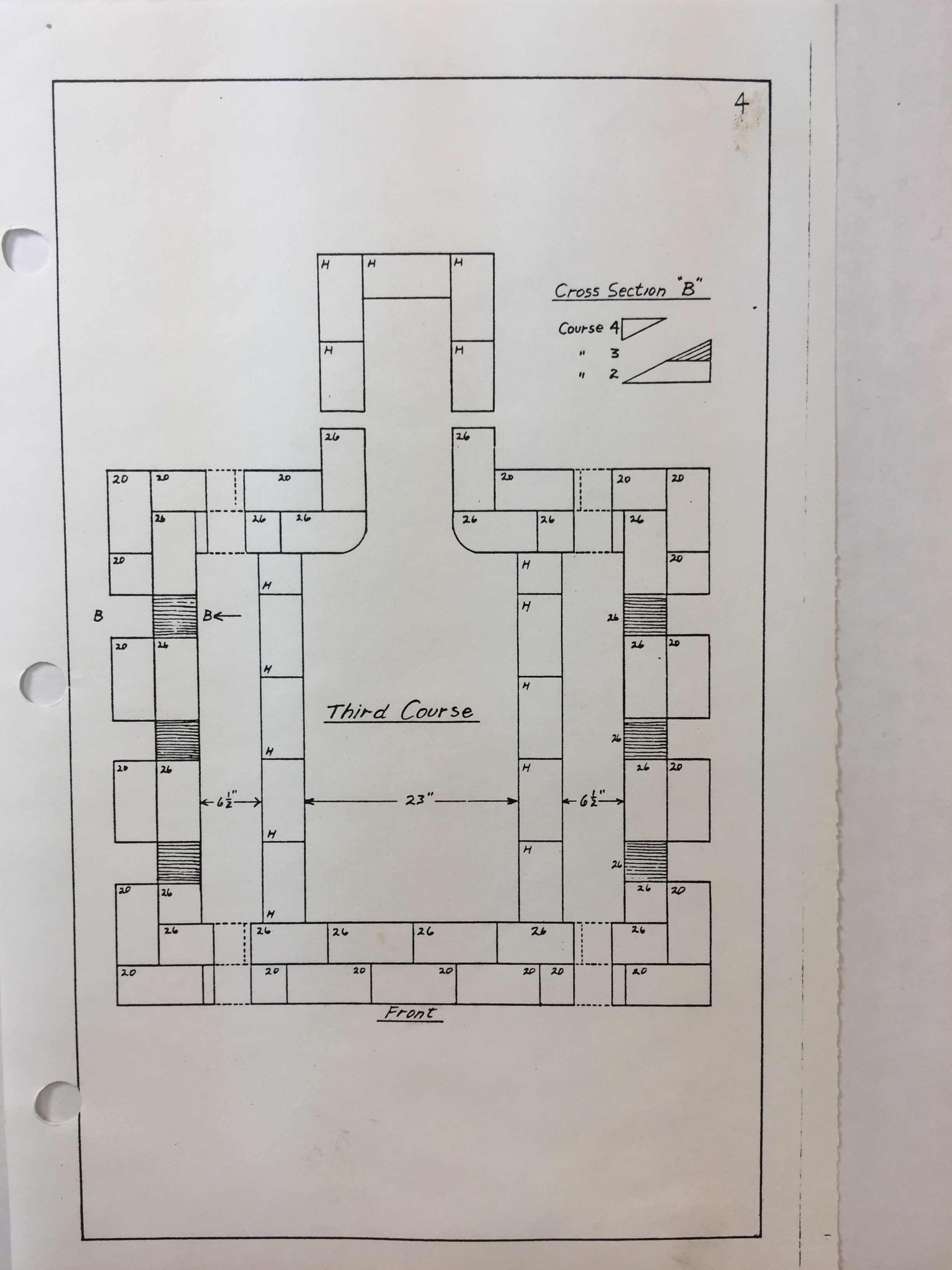
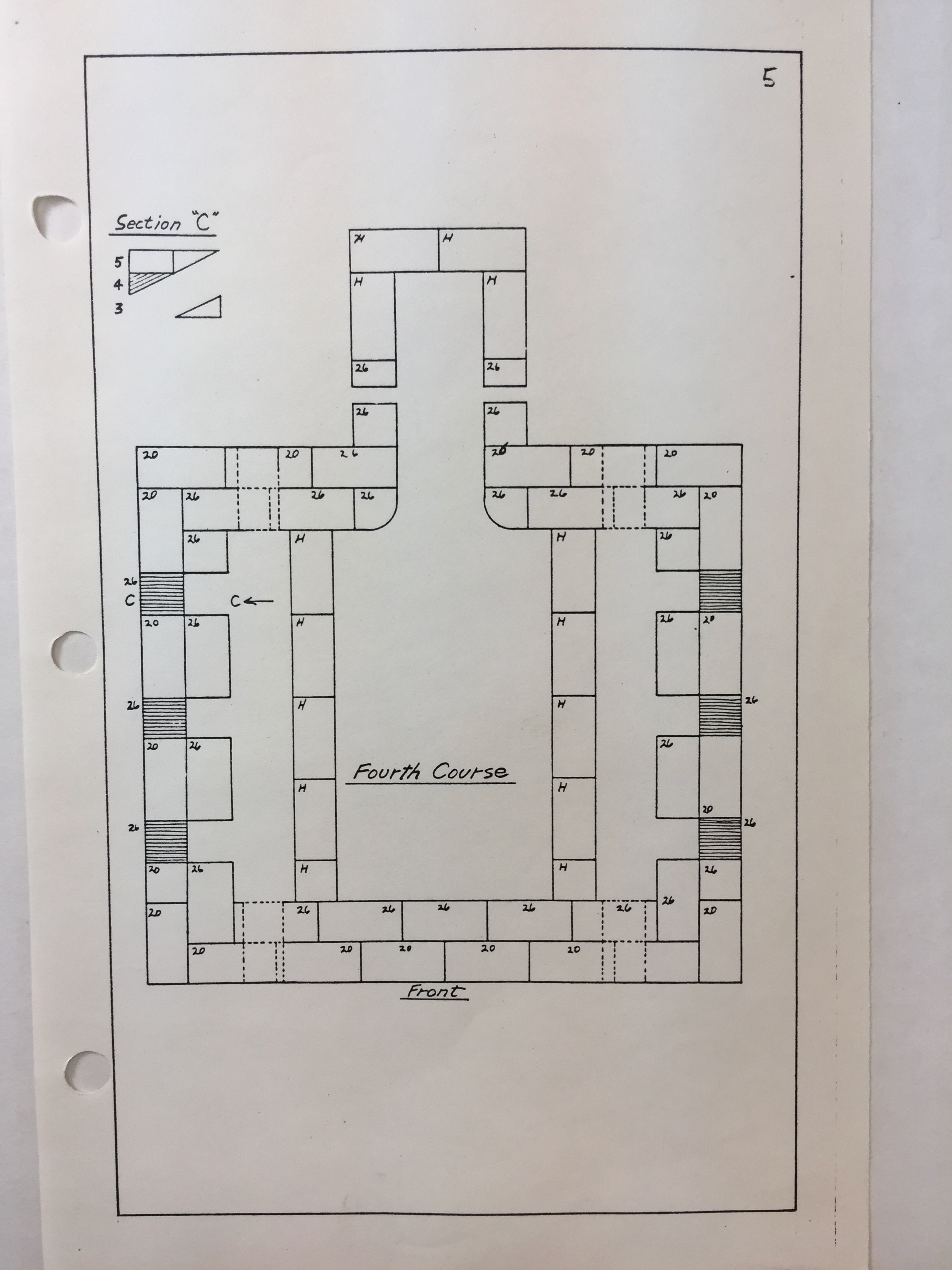
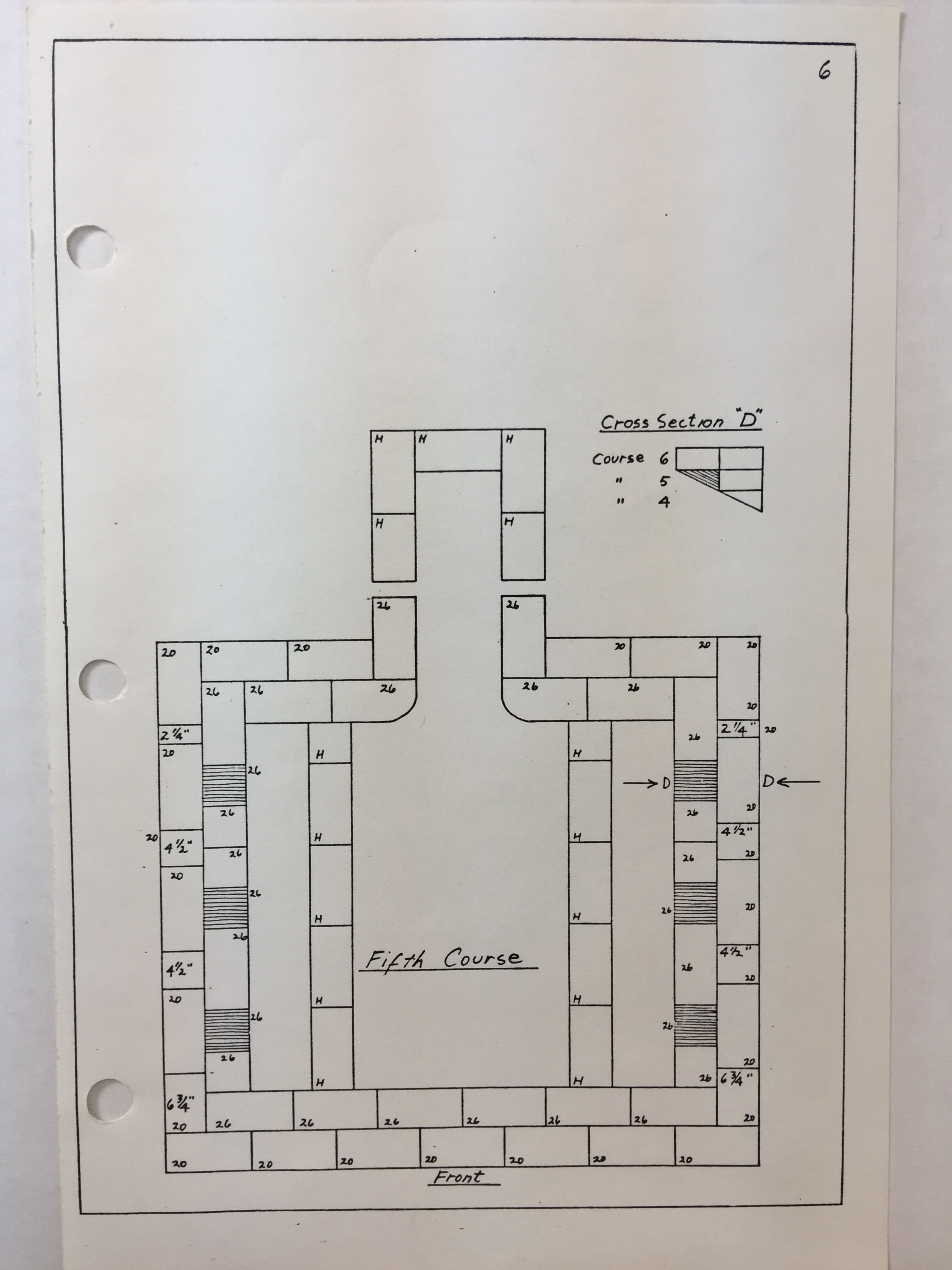
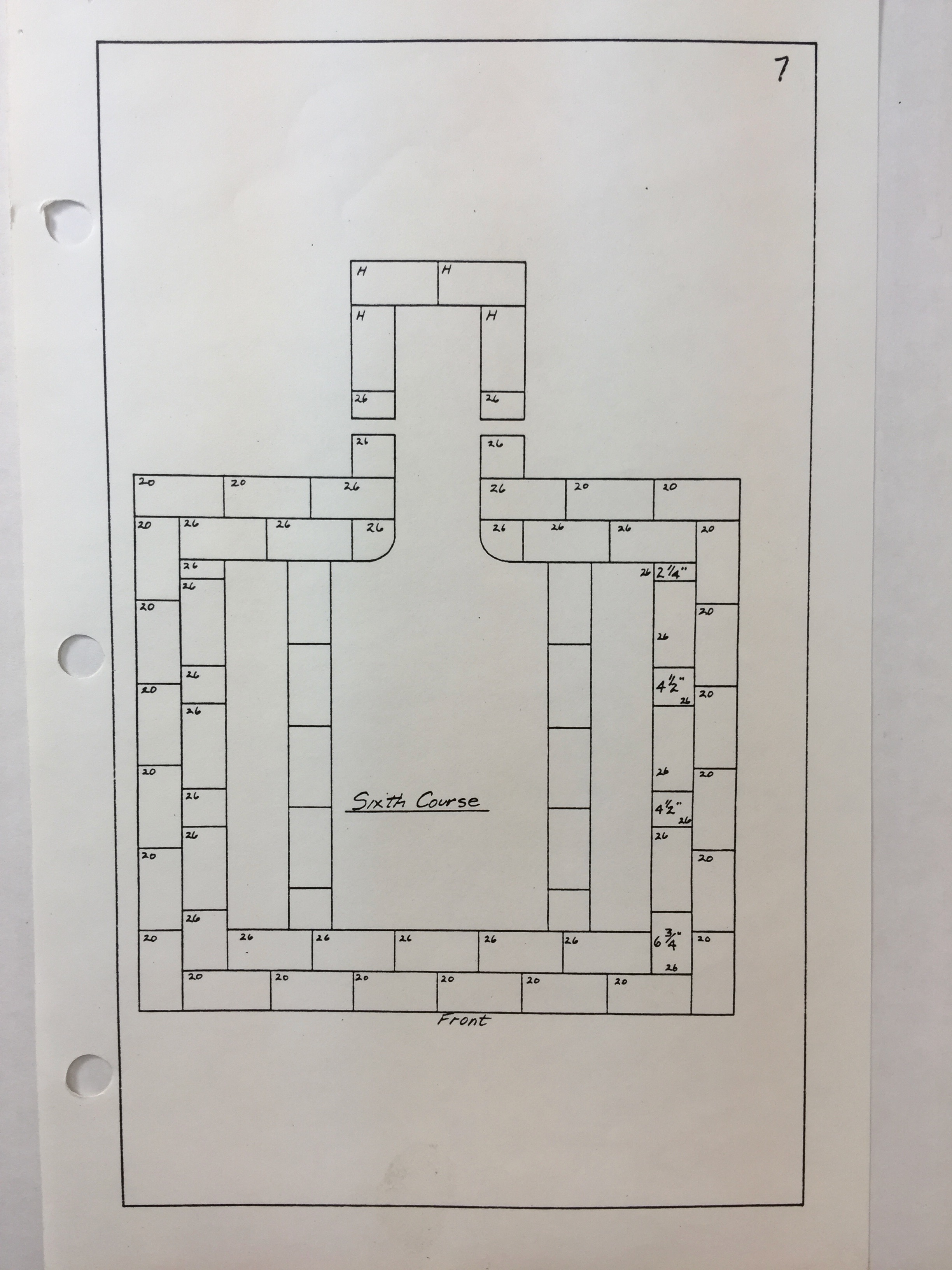
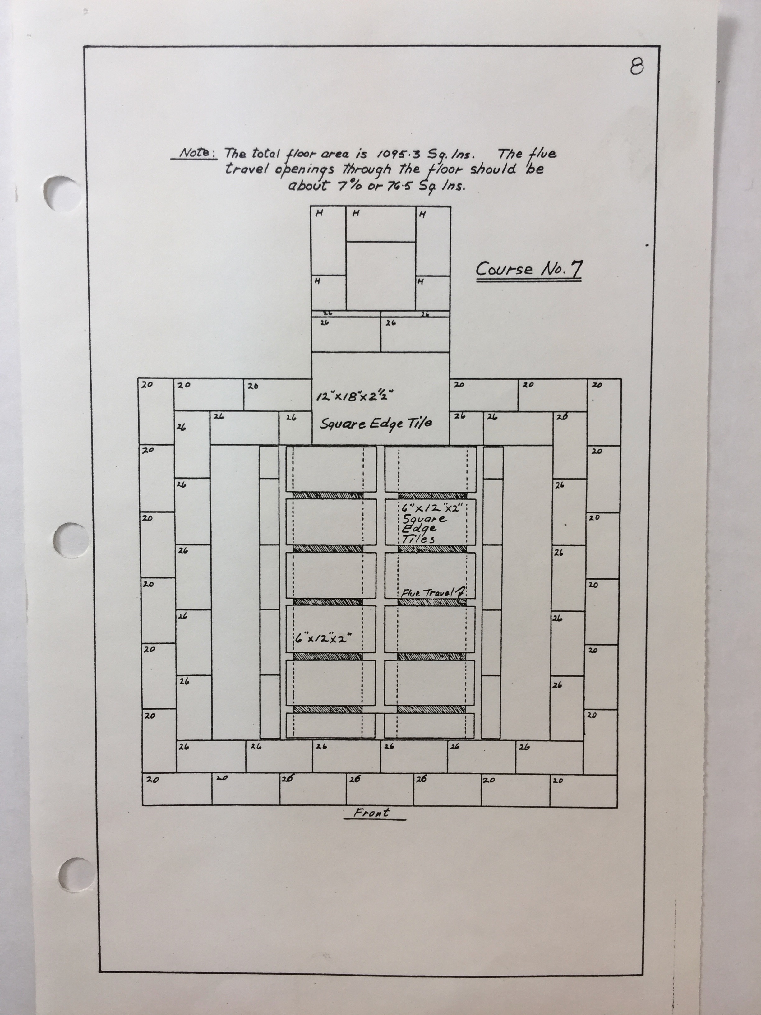
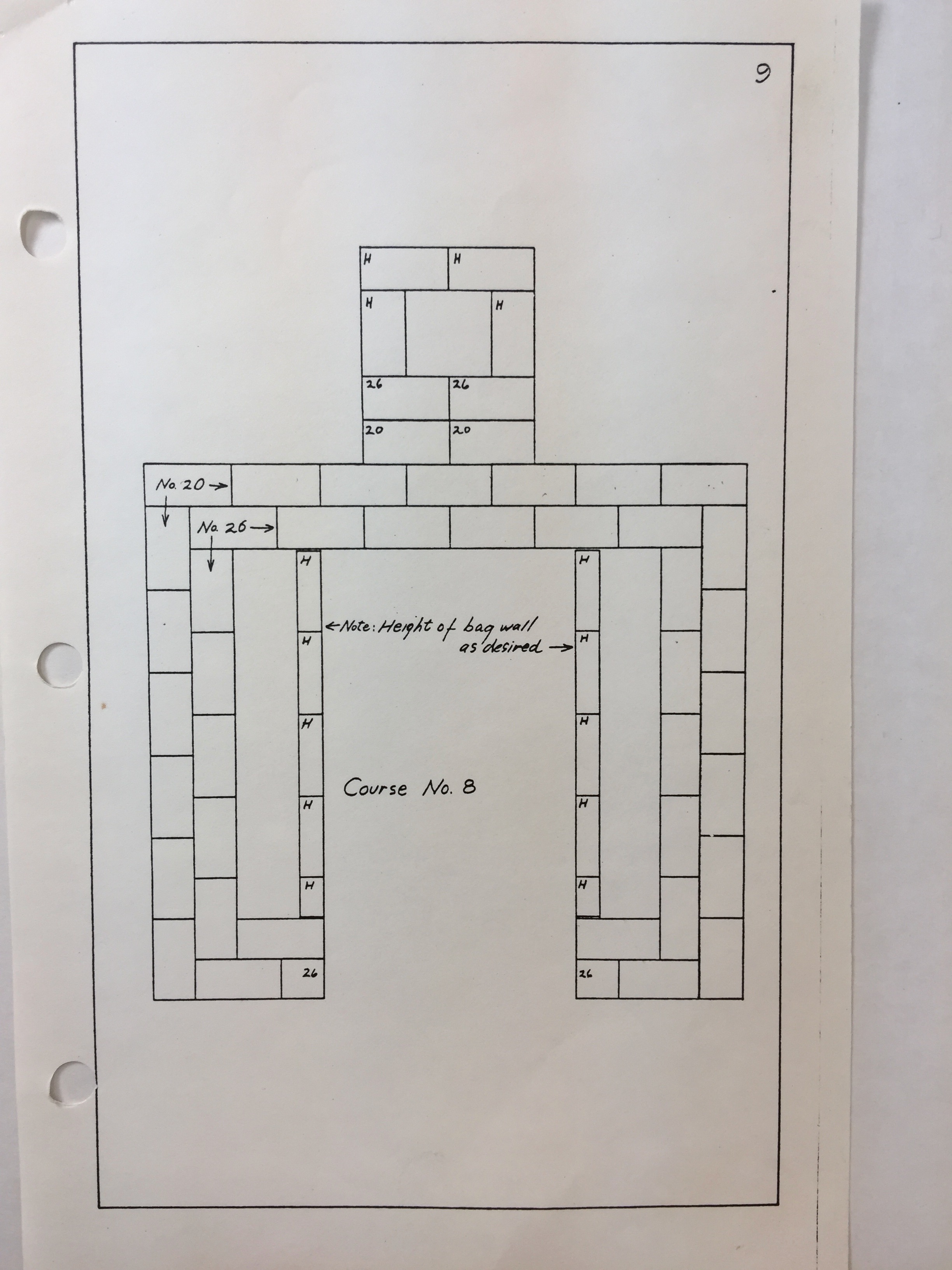
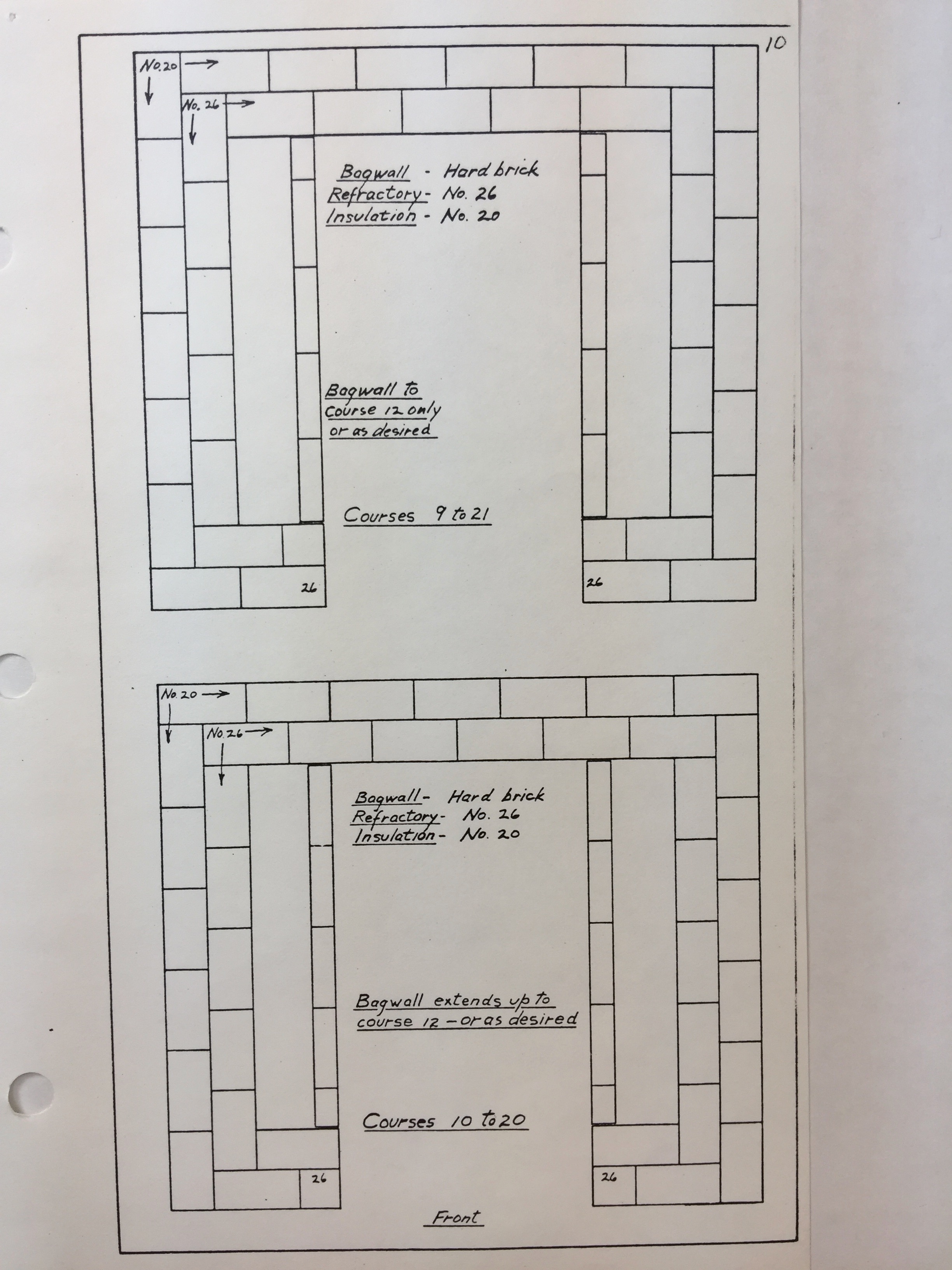
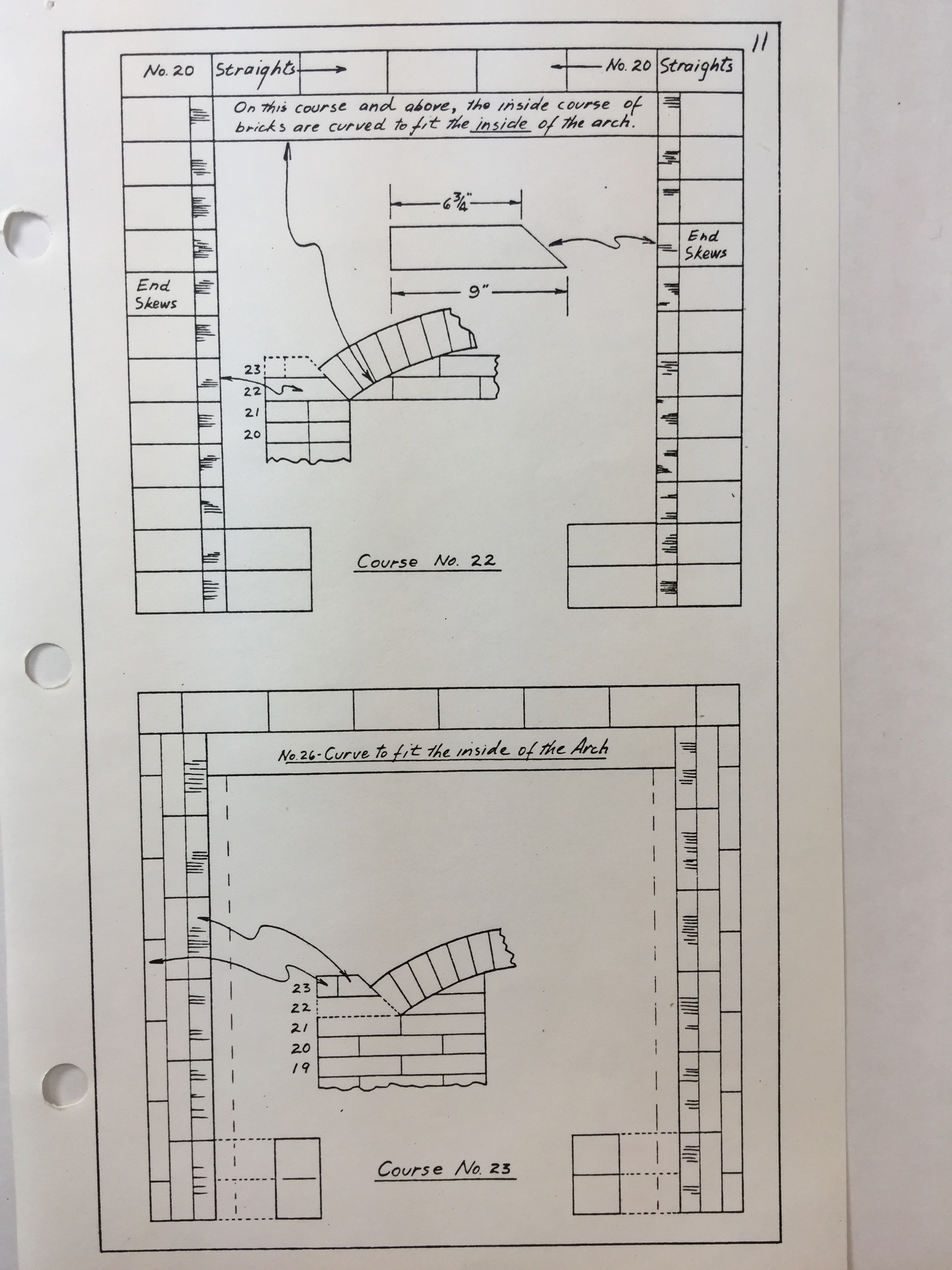
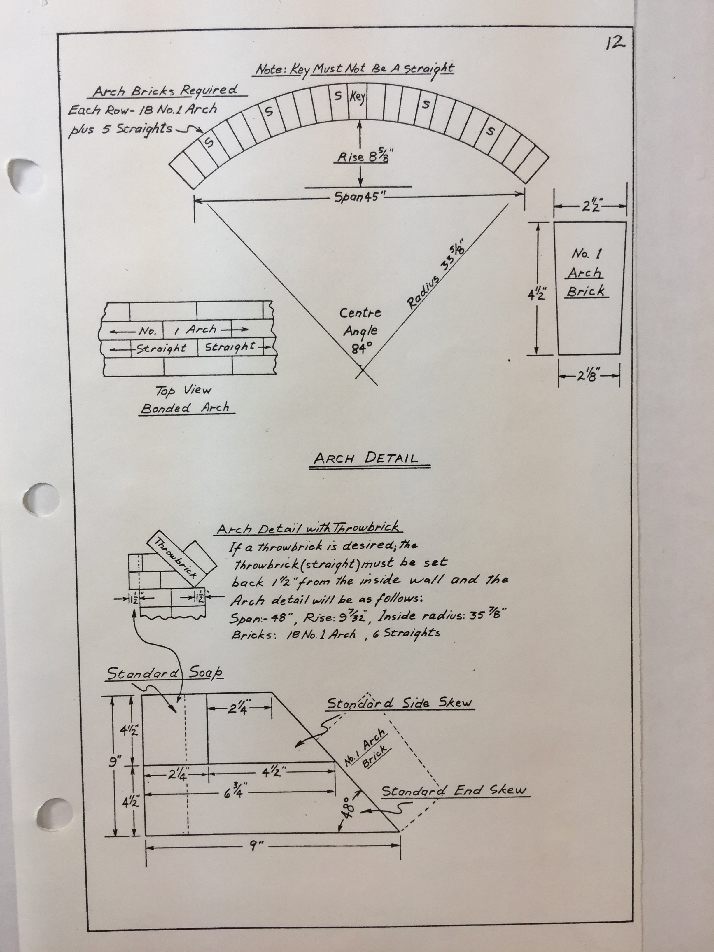
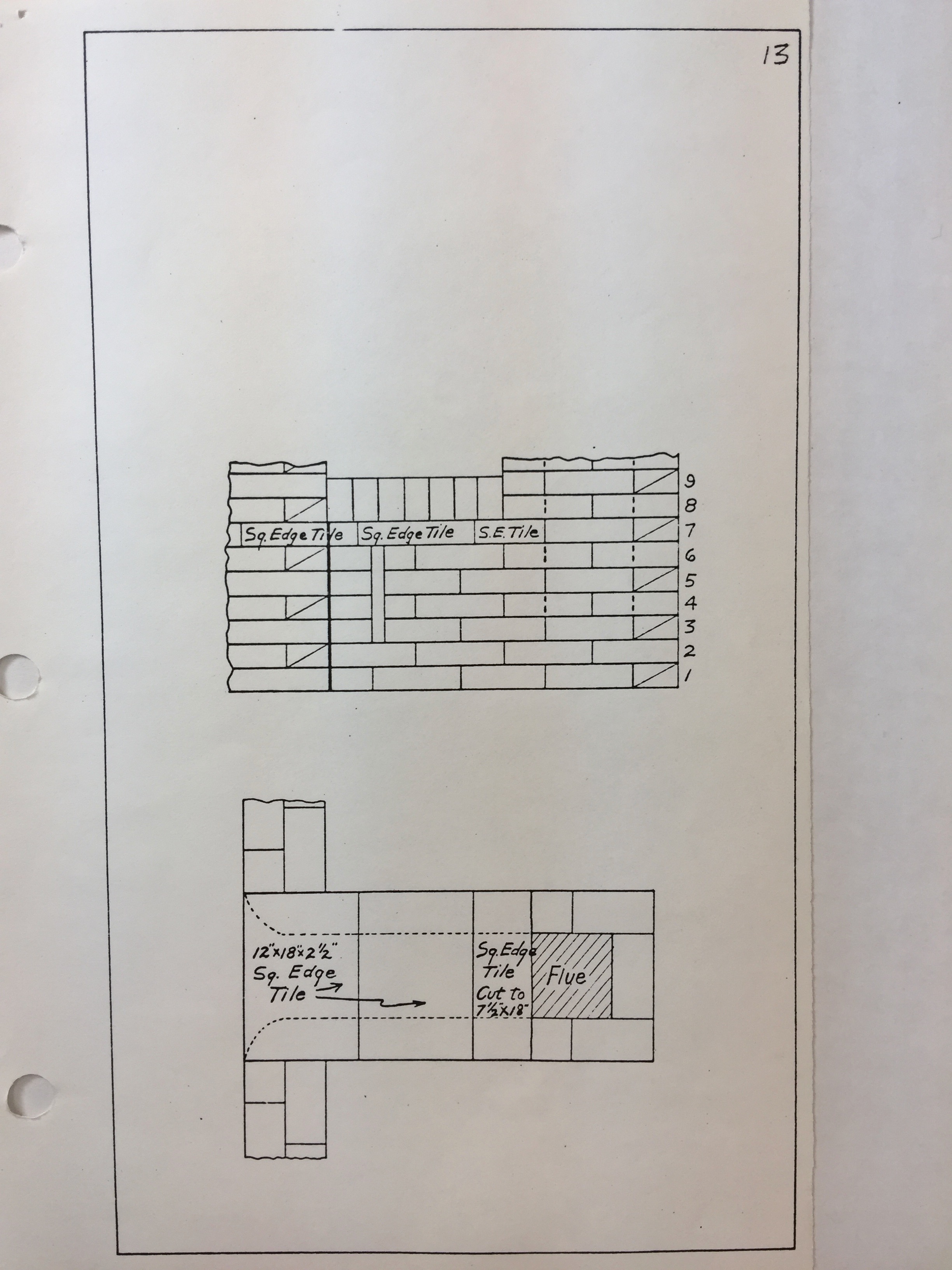
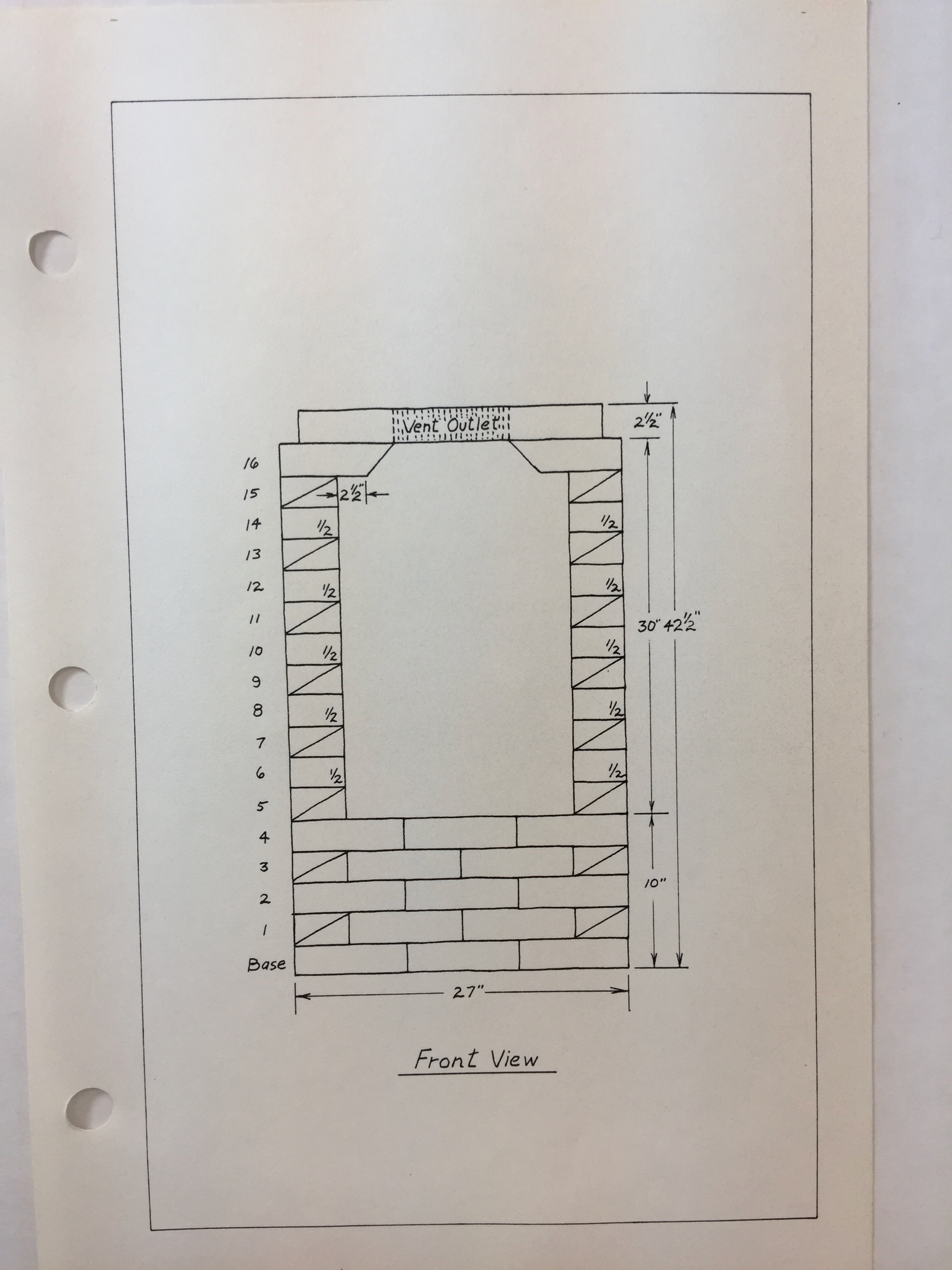
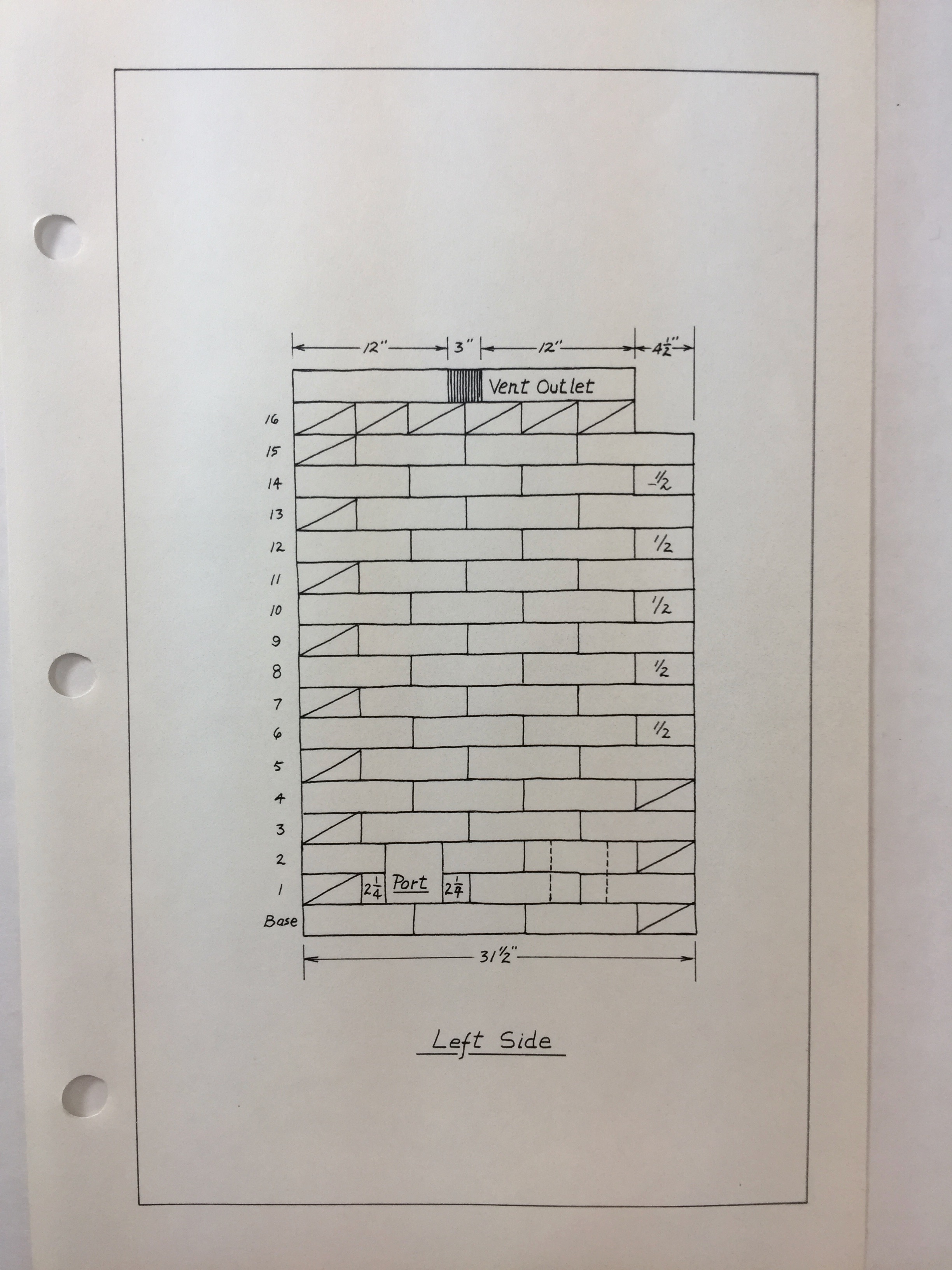
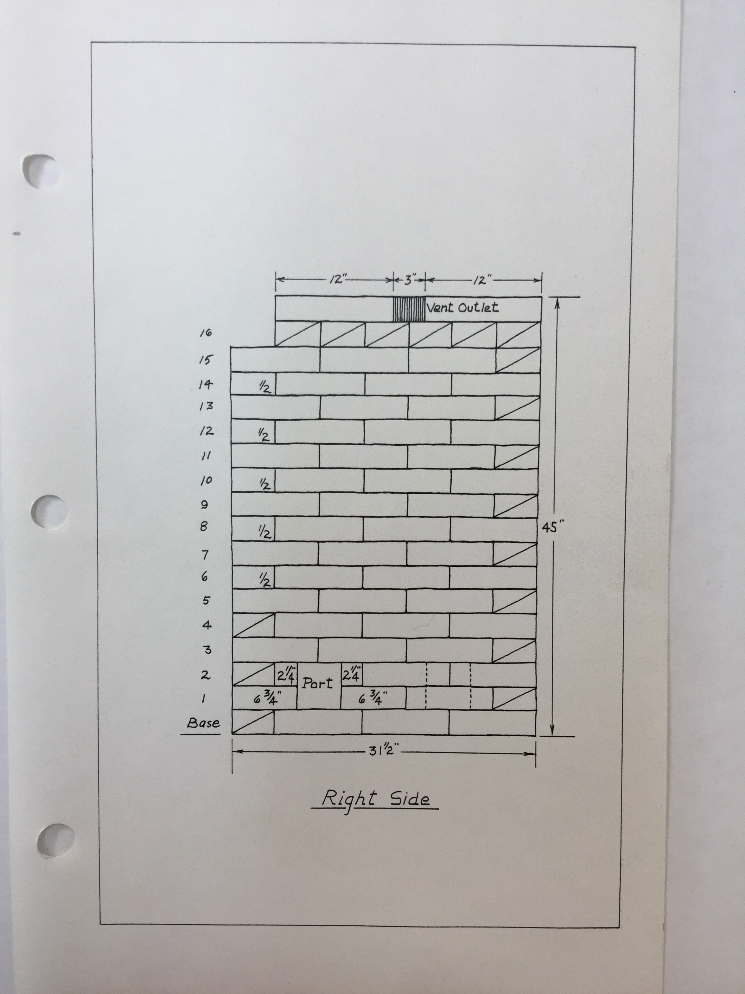
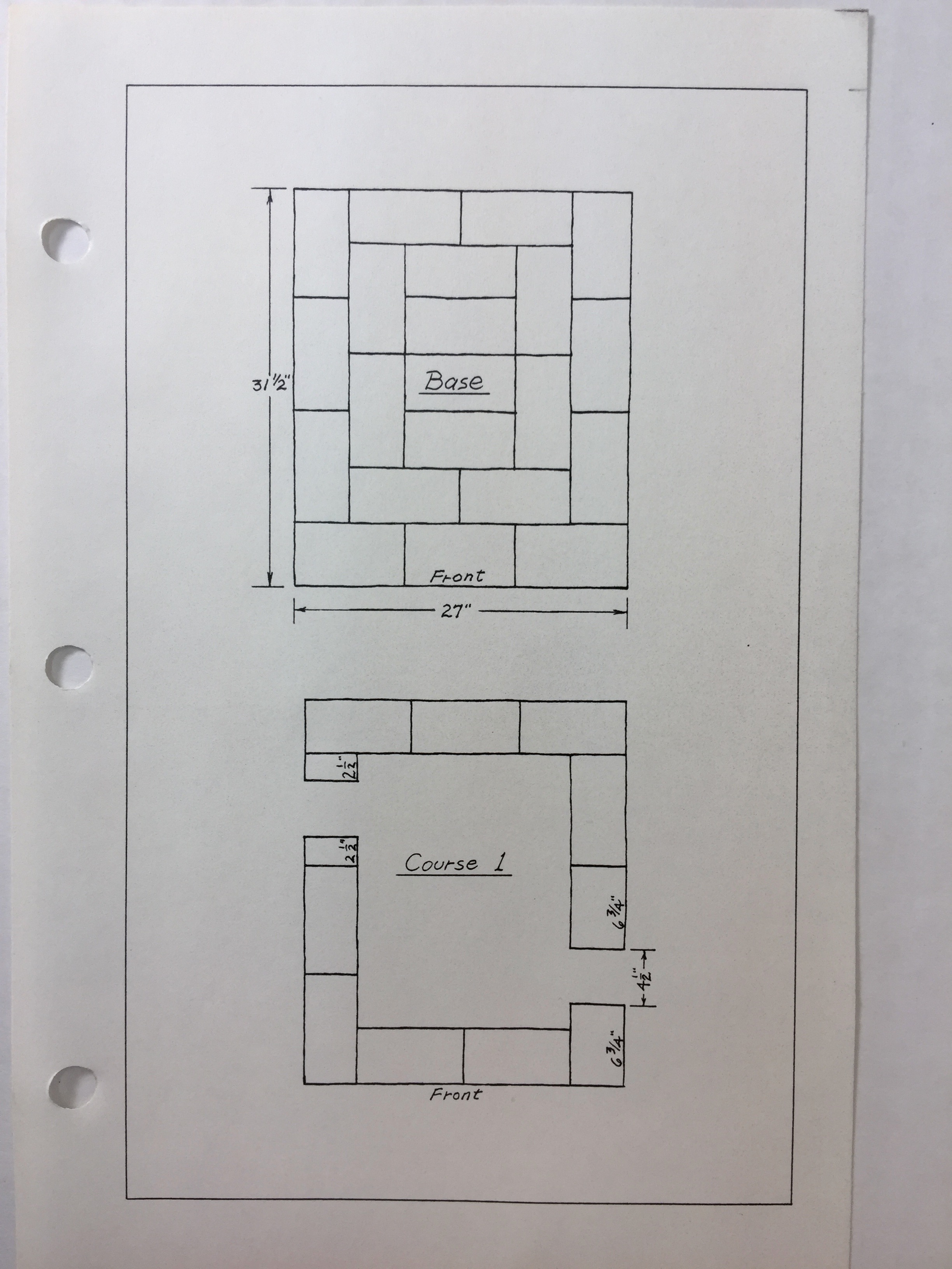
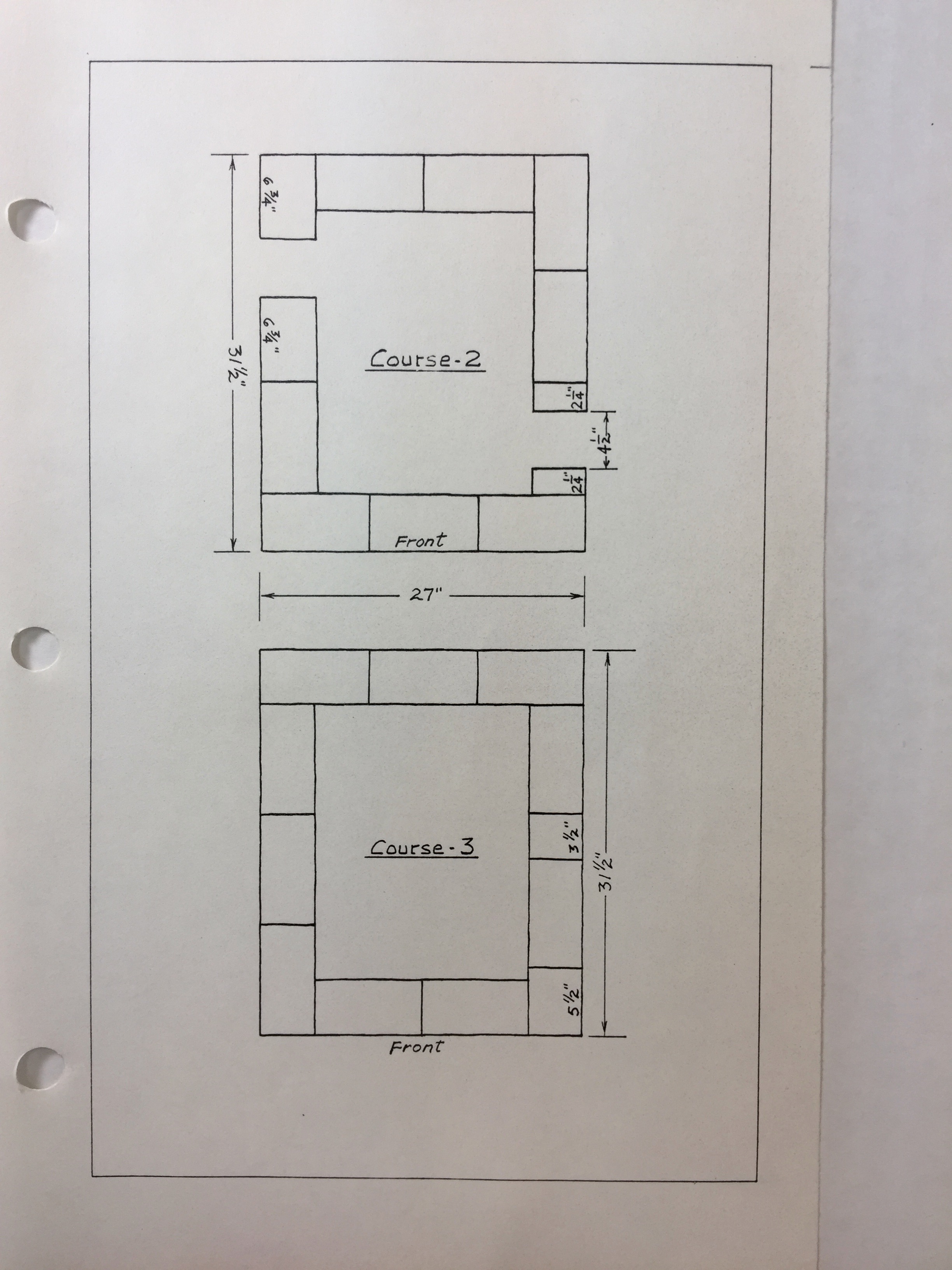
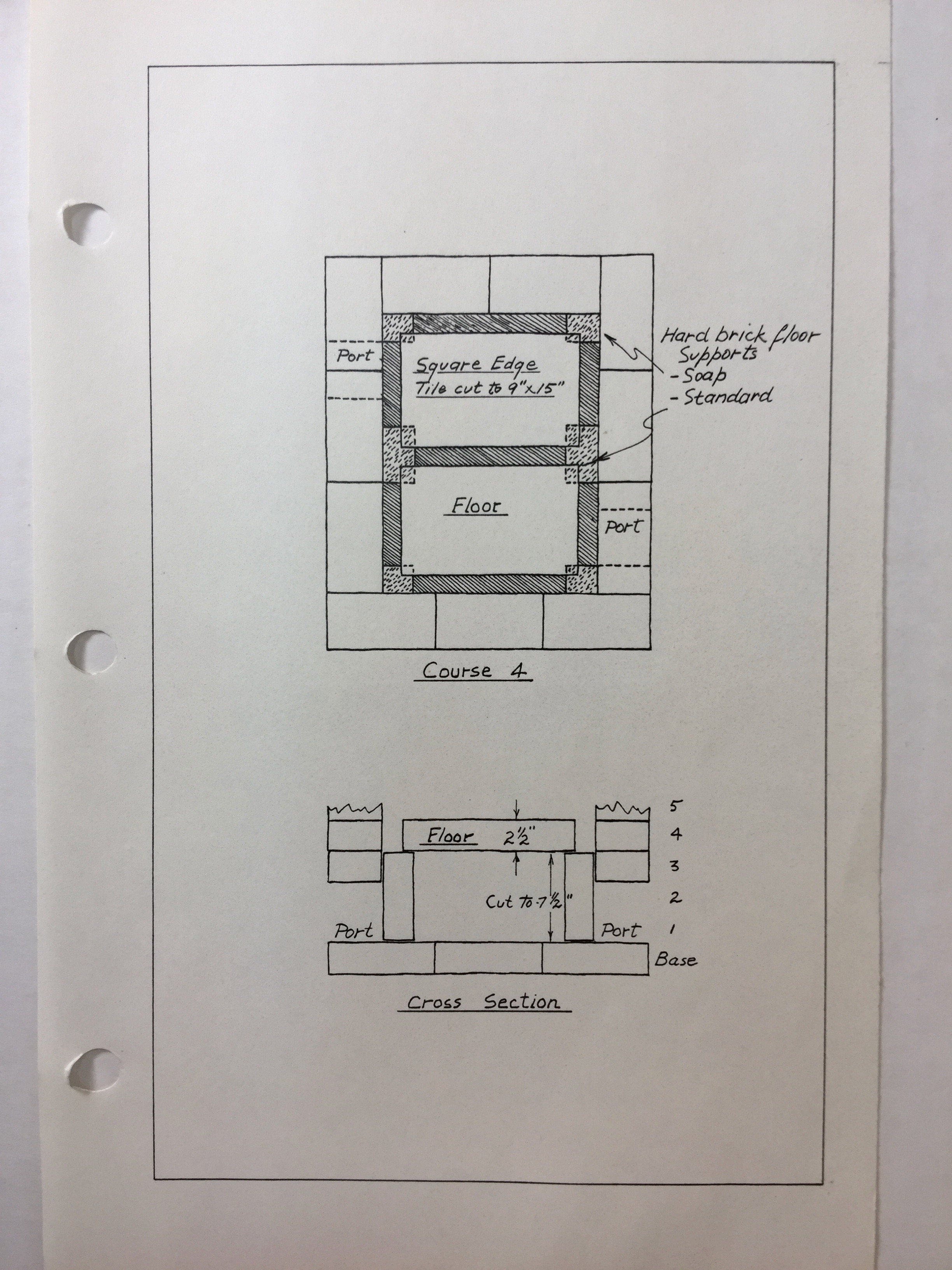
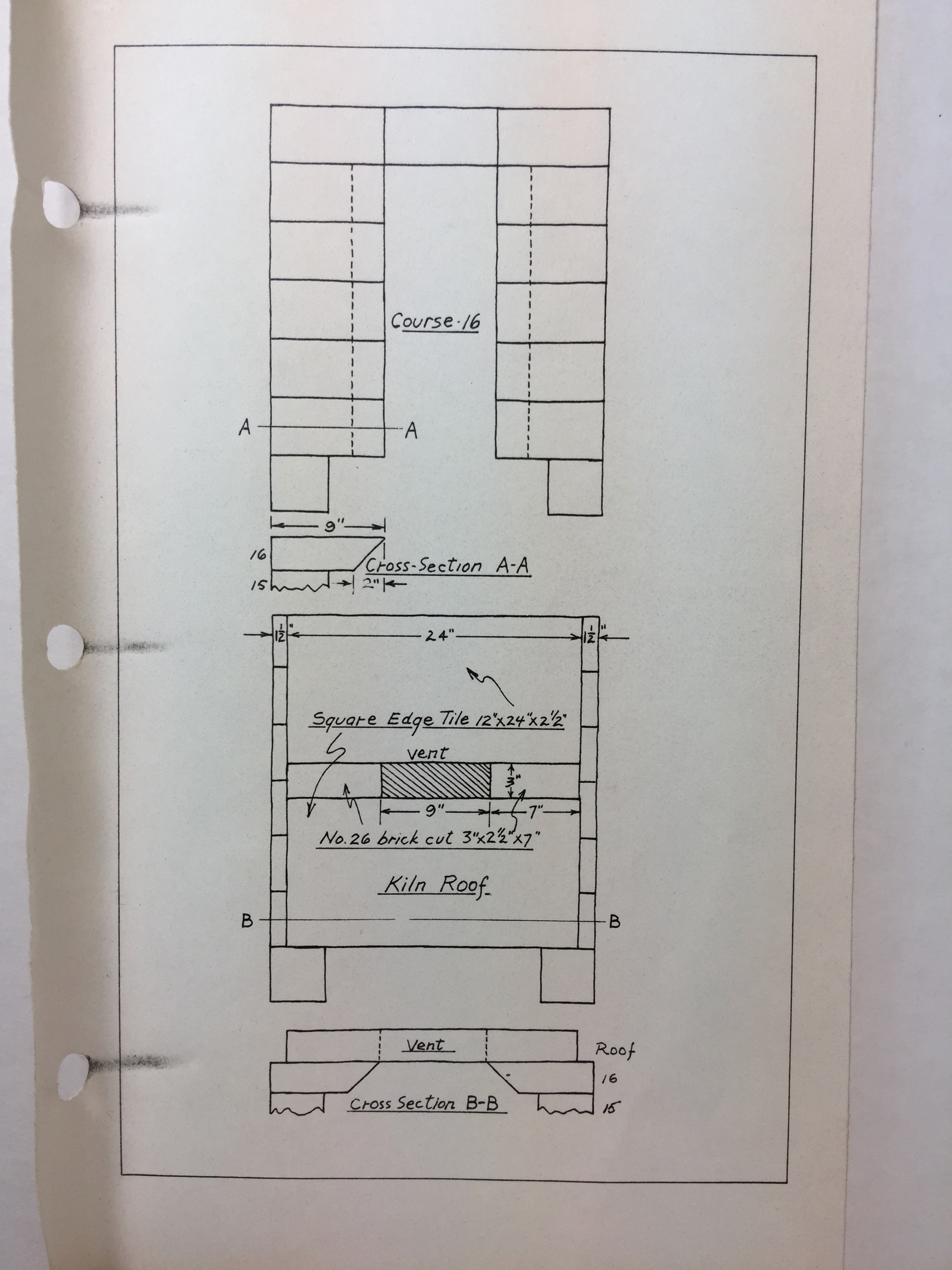
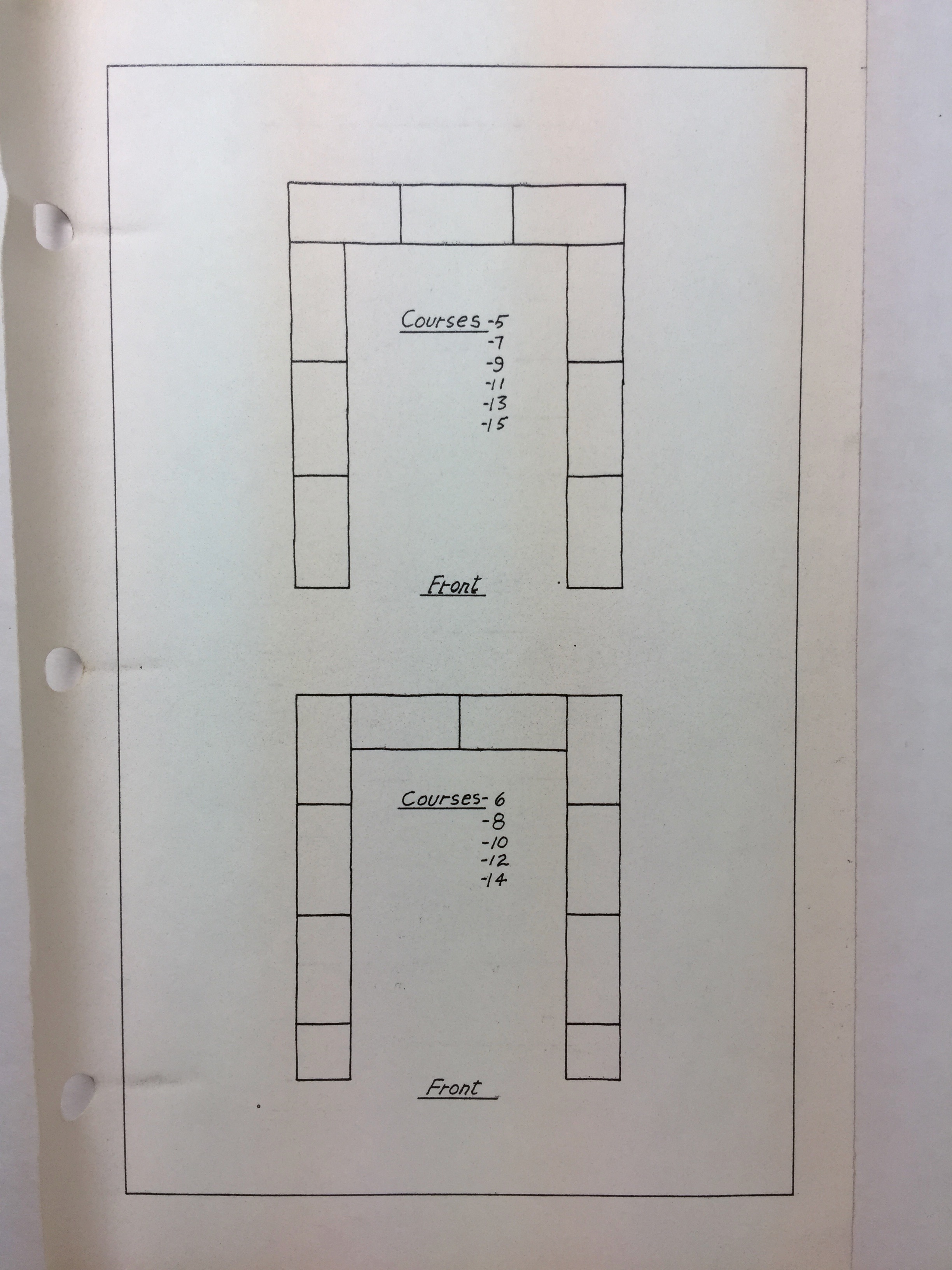
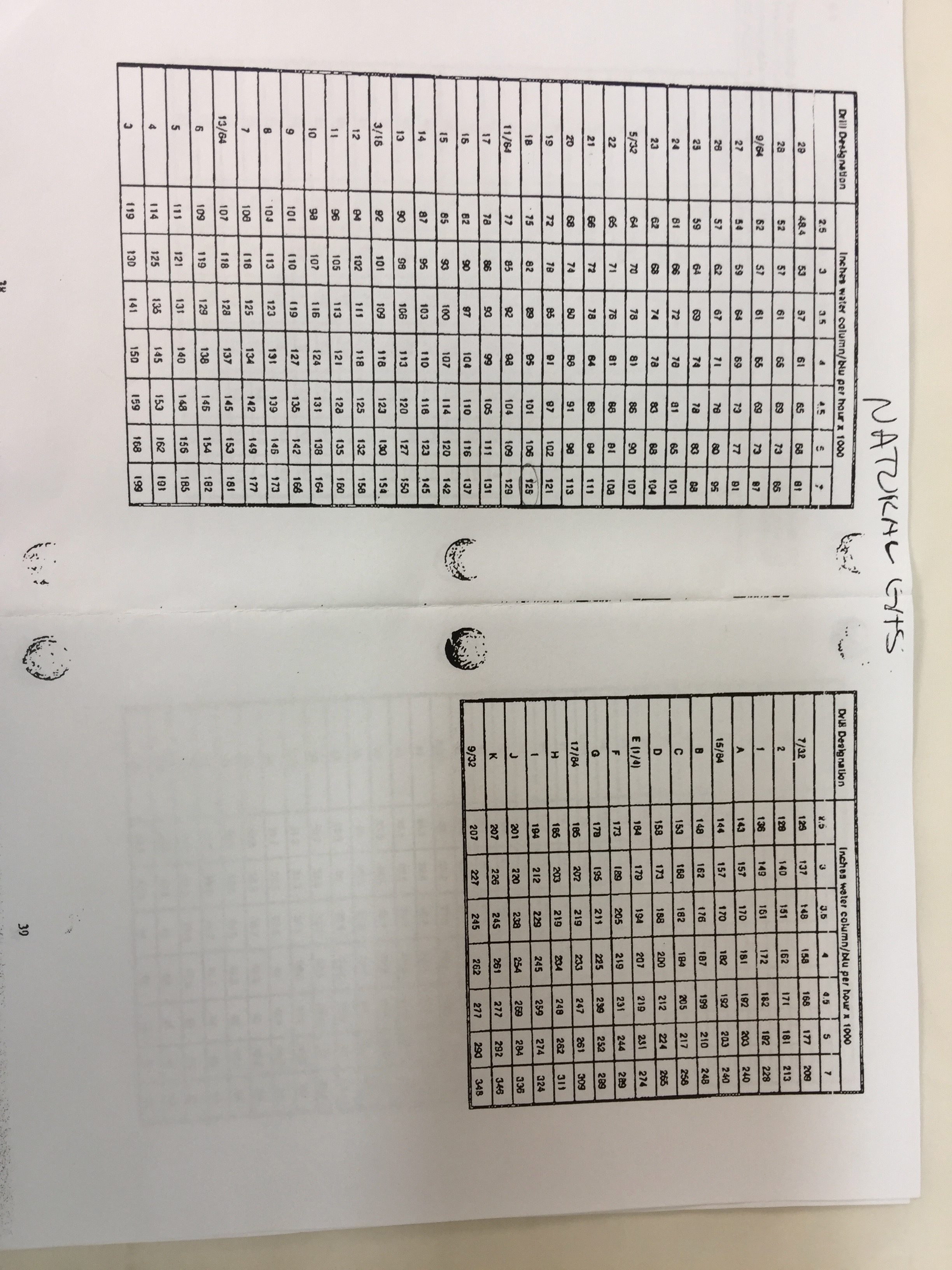
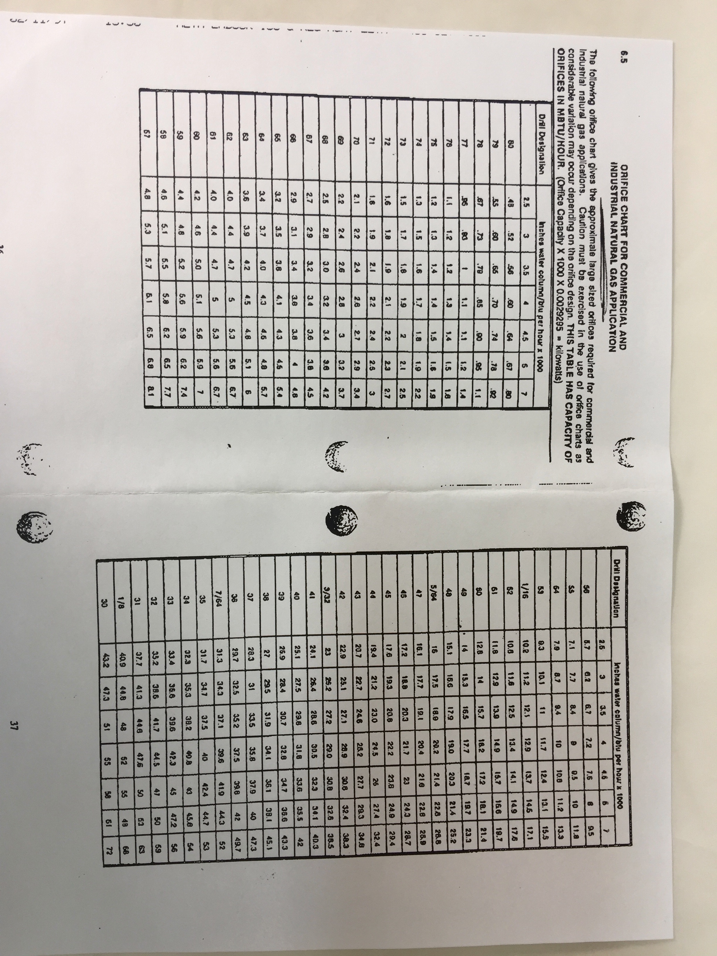